


RS4203 Manual
Chapter 2 - Safety Instructions
Rev 32, 01/11/13
Copyright © 2013, Tipper Tie, Inc., All rights reserved
21
2.4 Capital Equipment Safety Circuit Overview
Note: Existing machines that use a programmable logic controller (PLC) adhere to the statements in this
section although previous issues of this manual do not contain these statements.
Tipper Tie equipment that uses a PLC also contains an independent safety circuit, which is either a
programmable safety module or safety relay. Therefore, all safety related functions are controlled by an
approved safety controller/relay that is not dependent on the program contained in the PLC. The control
module monitors all E-Stop pushbuttons and all guard safety switches. Should one of the switches
change state, the control module opens a contact, which removes all power from the main air supply
valve, all PLC outputs (associated with pneumatic valving), and/or electrical actuators (motors etc.).
Although not part of the safety circuit, one input to the PLC is used to monitor the status of the safety
circuit. The program ensures that no outputs are on while the guards are open. Because this is controlled
by software, it is included in addition to the primary safety device.
Each safety switch contains one normally open contact and one normally closed contact. Both contacts
must change state as the door is closed in order for the safety circuit to reset. The presence of two
contacts per switch provides for redundancy, because either contact alone can trigger the safety circuit to
shut down all output power to the actuators. This prevents component movement even if a PLC output
would fail in the ON state.
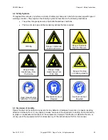
2.5 Warnings and Cautions
When using this machine, observe all instructions, warnings and precautions. Failure to comply could
result in serious injury, including cuts or crushed bones.
Warning
: Do not drill into or weld attachments on the frame of the machine.
Warning
: Do not modify, remove, disable, discard, or bypass guards or safety circuits.
Warning
: Do not operate the machine unless the safety circuit is operating correctly. The safety circuit
will remove power from the air and electric systems immediately upon the opening of the guards.
Warning
: Stop the machine to correct malfunctions by pressing the Emergency Stop button on the
operator interface or on the remote interface panel. Correct and clear obstructions or malfunctions before
restarting. Do not try to operate the machine by continuing to reset. Stop the machine, identify the
problem, and correct it. Report all malfunctions to the person in charge.
Warning
: The maximum operating pressure for this machine is 90 PSI (6,1 bar). Air
pressure greater than this could cause an explosive rupture in the air lines or pneumatic
components. Failure to adhere to this warning could result in personal injury or damage
to the machine.
Warning
: If a clip or other obstruction jams in the die area, do not attempt to cycle the machine again
until the jam is cleared. Turn off and lock-out the air supply before attempting to remove the obstruction.
Then, carefully remove the clip or obstruction to avoid damaging the clipper.
Warning
: Keep hands, fingers, jewelry and clothes clear of
the clipper’s die, punch, and knife areas.
Caution
: It is especially important to ensure both personnel and product safety that you carefully and
frequently inspect the clipper for worn parts. Check the die support channel and punch assembly, the
die and die pocket area of the die support, the clip pusher assembly and the knife assembly.


