background image

39

ED50

08-2018

DL4614-140

dormakaba ED50 OHC Installation Instructions

Chapter 17

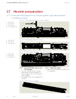
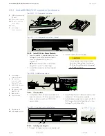
PCB holder 
assembly, Terminal 
PCB DC4630

2

  Low voltage 

terminal PCB

2.1

  Ribbon cable 

connector

3

  1/4-20 x 1/2" 

SBHCS

4

  1/4" square nut, 

installed in header 
track

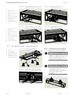
17.4  Install low voltage terminal PC board module

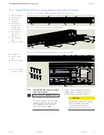
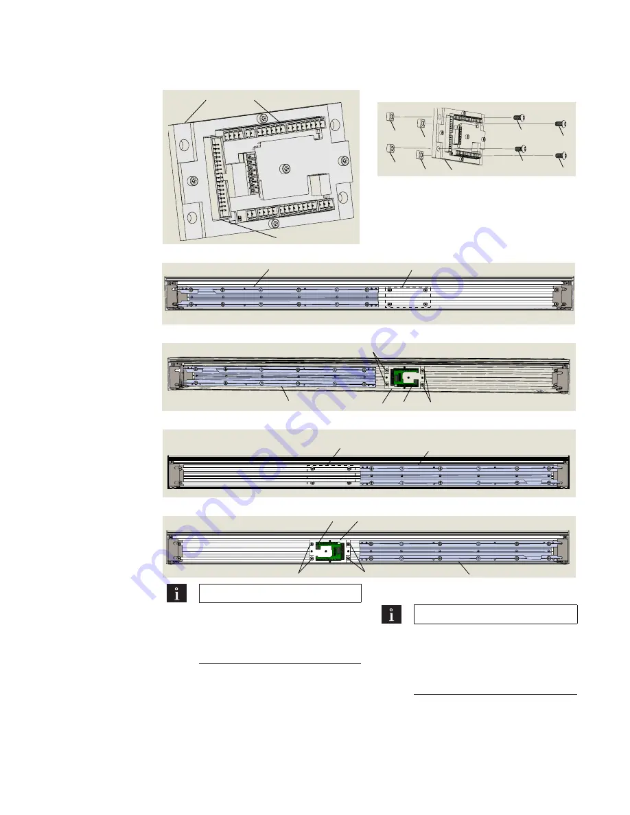
Fig. 17.4.1  Terminal PC board module

1

2

2.1

4

4

4

4

3

3

3

3

1

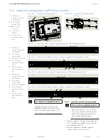
Fig. 17.4.6  Terminal PC board module 

fasteners

Fig. 17.4.3  Terminal PC board module installed in header; ED50 operator on left

3

3

1

2

6

Fig. 17.4.5  Terminal PC board module installed in header; ED50 operator on right

Fig. 17.4.4  Fasteners for Terminal PC board module; ED50 operator on right

PCB holder 
assembly, Terminal 
PCB DC4630

2

  Low voltage 

terminal PCB 

3

  1/4-20 x 1/2" SBHCS

4

  1/4" square nut, 

installed in header 
track

5

  OHC mounting 

plate installed on 
left

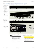
Fig. 17.4.2  Fasteners for Terminal PC board module; ED50 operator on left

PCB holder 
assembly, Terminal 
PCB DC4630

2

  Low voltage 

terminal PCB

3

  1/4-20 x 1/2" SBHCS

4

  1/4" square nut, 

installed in header 
track

6

  OHC mounting 

plate installed on 
right

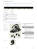
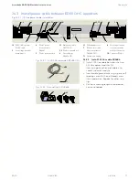
TIPS AND RECOMMENDATIONS

Ribbon cable from ED50 OHC 
operator connects to connector 
on Terminal PC board (Fig. 17.4.1).

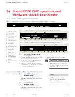
17.4.1  Install Terminal PC board module.

TIPS AND RECOMMENDATIONS

Refer to Figures 17.4.3 through 
17.4.6 for module installation for 
ED50 OHC operator located on 
right or left side of header.

1.  Install module in header using fasteners 

(3,4) installed in header tracks. Do not 
over-tighten SBHCS's.

2.  Position module in header track as 

shown in Fig. 17.4.3 or 17.4.5.

5

4 sets

 3,4

6

4 sets


3,4

1

2

5

3

3

Содержание ED50 OHC

Страница 1: ...ED50 Low Energy Operator Installation in Overhead Concealed Header Installation Instructions DL4614 140 08 2018 EN ...

Страница 2: ...ng doors 29 Table of contents 14 ED50OHCinstallationtemplate 30 14 1 Header installation 30 14 2 Bottom pivot floor installation 31 14 3 Program panel jamb cutout 32 14 4 RJ45 panel jamb cutout double doors 33 15 Reserved 16 Customer installed door jambs 34 16 1 Check jamb installation dimensions 34 16 2 Check jambs for plumb level and square 35 16 3 Drill holes in jambs for header mounting and fo...

Страница 3: ... ED50 OHC firmware viewing and changing parameters 80 31 6 ED50 OHC configuration parameters 81 31 7 Set configuration parameters double door 82 31 8 ED50 OHC power on 83 31 9 Perform partial learning cycle to rotate arm to door installation position for each ED50 operator 84 32 Double door installation 86 32 1 Customer supplied doors double door installation 86 32 2 Perform learning cycle for eac...

Страница 4: ...ba com website 1 4 Symbols used in these instructions WARNING This symbol warns of hazards which could result in personal injury or threat to health NOTICE Draws attention to important information presented in this document 1 General information TIPS AND RECOMMENDATIONS Clarifies instructions or other information presented in this document 1 5 Dimensions Unless otherwise specified all dimensions a...

Страница 5: ...ng doors 2 2 Packaging The ED50 operator is packaged in a header for overhead concealed OHC installation For double swing doors two ED50 operators are packaged in a single header 2 2 Low energy operator The ED50 is supplied only as a low energy operator ANSI BHMA A156 19 The operator is supplied with a reduced power motor and a brake The brake is used during door hold open time WARNING To reduce r...

Страница 6: ...tion mayresult from an incorrect installation WARNING Hazard to mechanical processes by use of control settings elements or procedures not documented in this manual WARNING Electric shock hazard By use of control elements settings or procedures not documented in this manual WARNING Work on electrical equipment and 115 Vac wiring installation must be performed only by qualified personnel WARNING Me...

Страница 7: ...tions 4 1 ED50 OHC single door configurations Fig 4 1 1 LH inswing RH inswing Fig 4 1 2 LH outswing RH outswing Fig 4 2 4 RH double egress Fig 4 2 3 Inswing Fig 4 2 1 Outswing Fig 4 2 2 LH double egress 4 2 ED50 OHC double door configurations Jambs and doors supplied and installed by customer Locks optional ...

Страница 8: ... 3 Fig 5 1 3 ED50 OHC header RH outswing 3 Fixed stop Reference Para 17 7 for alternative fixed stop 1 2 Header RH outswing 2 Overhead arm 3 Fixed stop Reference Para 17 7 for alternative fixed stop 1 4 Header LH inswing 2 Overhead arm 4 Breakout switch 1 4 2 4 Fig 5 1 4 ED50 OHC header LH inswing Fig 5 1 2 ED50 OHC header RH inswing 1 3 2 4 1 3 Header RH inswing 2 Overhead arm 4 Breakout switch 3...

Страница 9: ...4 5 1 1 Header LH outswing 1 2 Header RH outswing 1 3 Header RH inswing 1 4 Header LH inswing 2 Header track 3 Operator drive axle hole 4 Mounting hardware low voltage wiring module 5 Cutout and mounting holes for breakaway switch or fixed stop for outswing door 6 Mounting holes for door stop Fig 5 2 4 RH outswing header assembly 1 2 2 3 4 6 Fig 5 2 1 LH outswing header assembly Fig 5 2 2 RH inswi...

Страница 10: ...Main power cable DK3772 010 4 Main power extension cable DX4647 010 5 PCB holder assembly DC4630 010 5 1 Connection point circuit board 6 Ribbon cable 7 Ground wire kit 3 Fig 5 4 5 115 Vac power cable Fig 5 4 1 115 Vac power module 5 5 1 Fig 5 4 2 Low voltage wiring module 6 Fig 5 4 7 Ribbon cable 7 Fig 5 4 8 Ground wire kit DK3673 010 2 2 1 2 3 2 2 3 1 Connector 8 pole 2 Connector 6 pole 3 Connec...

Страница 11: ...to close 3 Doorshouldcloseataslow smooth pace 4 or more seconds and stop without impact 4 Inspect the floor area It should be clean with no loose parts that might cause user to trip or fall Keep traffic path clear 5 Inspect door s overall condition The appropriate signage should be present and the hardware should be in good condition 6 Have door inspected by an AAADM certified inspector at least a...

Страница 12: ...ir inswing 1 1 Header pair outswing 2 Overhead arm 3 Fixed stop Reference Para 17 7 for alternative fixed stop 1 2 Header pair inswing 2 Overhead arm 4 Breakout switch 1 3 Header LH double egress 2 Overhead arm 3 Fixed stop 4 Breakout switch Reference Para 17 7 for alternative fixed stop 1 1 Header RH double egress 2 Overhead arm 3 Fixed stop 4 Breakout switch Reference Para 17 7 for alternative f...

Страница 13: ...der track 3 Operator drive axle hole 4 Mounting hardware low voltage wiring module 5 Cutout and mounting holes for breakaway switch or fixed stop 6 Mounting holes for door stop Fig 6 2 1 Pair outswing header assembly Fig 6 2 2 Pair inswing header assembly Fig 6 2 4 RH double egress header assembly 1 4 2 2 3 3 4 5 6 4 1 1 2 2 3 3 4 4 6 6 Fig 6 2 5 Pair inswing header assembly example 1 3 2 2 3 3 4 ...

Страница 14: ...g 6 4 4 Screw pack header mounting DK4654 010 1 14 10 x 2 1 2 Phillips flanged hex head zinc 2 1 4 x 1 Phillips flanged hex head zinc 3 1 4 20 x 1 PH FLH Phillips flat head Fig 6 4 12 Screw pack ED50 operator mounting DK4617 010 1 Plug 1 1 2 2 Plug 10 mm 3 Door pivot 4 Screw pack 4 1 PHMS 1 4 20 x 3 4 4 2 FHMS 14 x 1 1 2 4 3 Anchor 5 Wrench height adj 6 Floor pivot 7 Bearing Fig 6 4 13 Bottom pivo...

Страница 15: ...RMATION Low Energy Swinging Doors 1 Activate the door Door shouldopen at a slow smooth pace 4 or more seconds and stop without impact 2 Doormustremainfullyopen foraminimumof5seconds before beginning to close 3 Doorshouldcloseataslow smooth pace 4 or more seconds and stop without impact 4 Inspect the floor area It should be clean with no loose parts that might cause user to trip or fall Keep traffi...

Страница 16: ...e 8 115 Vac power cable 9 115 Vac power 1 Control board 2 Keypad and 2 digit display 3 Braking circuit plug 4 Power fail closing speed potentiometer 5 Upgrade card slot 5 1 Upgrade card socket 6 dormakaba handheld communication port 7 Pair door operator to operator communication port 8 Ribbon cable socket 9 Program switch panel socket Fig 7 1 3 ED50 operator control board 1 2 3 4 5 5 1 6 7 8 9 2 5...

Страница 17: ...acket 7 End cap 8 ED50 OHC operator RH door 9 Low voltage wiring connection PCB module RH door 10 115 Vac power connection PCB module RH door 11 115 Vac power cable 12 Fixed stop outswing 13 Ground lug 14 115Vac cable between operators TIPS AND RECOMMENDATIONS Ribbon cables not shown for clarity Fig 7 2 2 ED50 OHC operator hardware Fig 7 2 3 115 VAC Power cable between operators 1 115 Vac power ca...

Страница 18: ...ive control Driving phase optimization Cycle counter CC parameter 0 to 1 000 000 Power assist function hA hF hS parameters Drive support for manual opening of door Push go function PG parameter Auto opening of door at 4 open 8 1 ED50 Technical data 8 1 1 Required operating conditions Ambient temperature 5 to 122 F Suitable for dry rooms only Relative air humidity 93 maximum non condensing Power su...

Страница 19: ...on Once angle reached drive support provides easier manual opening of the door Parameter hF power assist function Parameter values greater than 0 provides additional opening force Parameter hS power assist function support for door in closed position 8 2 1 ED50 low energy operator Maximum power consumption 120 watt Automatic opening torque Minimum 20 N m 14 8 lbf ft Maximum 67 N m 49 4 lbf ft Auto...

Страница 20: ...ameter values error and information codes 10 2 2 4 button keypad 4 button legend can be orientated so buttons have same function and position regardless of operator orientation Button legend can be removed and rotated 10 2 3 4 button keypad functions Downbutton 1 Scrollthroughparameters anderrormessages 2 Reduceparametervalue 3 Openingpulse press button 3s 4 Learningcycle press button 3s 5 Resetwi...

Страница 21: ... 3 1 Program switch control modes Auto door opens automatically when one of the activators is actuated or triggered and closes on expiration of adjustable hold open time with no activators or actuators triggered Close door closes automatically or remains closed until program switch position changed Open door opens automatically and remains open until program switch position changed 10 3 2 Exit onl...

Страница 22: ...ust be used 11 2 5 Miscellaneous accessories 1 Door status display red green 11 2 System accessories 1 Externalprogram switch mechanical 2 Externalprogram switch electronic 3 Keyswitch 4 Pushbutton night bank 5 Pushbutton interior 6 Pushbutton exterior 7 Door locking device 8 Manual release switch 9 ED50 OHC header 11 2 6 Activators Typical activators 1 Pushbuttons key switches 2 Radio systems 3 S...

Страница 23: ...grade card plug included in card scope of delivery 7 Fireprotectionupgrade card plug included in card scope of delivery 11 3 ED50 terminal board interface v1 7 Night bank 18K resistor not required 97 98 99 30 31 32 34 33 3 3 35 1 3 6 1 4 4a 3 B A 1 57 57a 1 42 3 1 41 3 1 15 17 3 1 11 13 3 43 3 64 63 62 1G 3 24 V Signal input 0 V Partial Open Permanent Open Exit Only Automatic Off N C COM Test outp...

Страница 24: ...nch 3 to 50 ft lb min 6 1 Metric hex keysockets 7 Open end wrench 13 mm 8 Screwdriver flat blade M2 1 16 to 3 32 2 4 7 Fastener size ft lb M5 3 7 M6 7 M8 17 M10 34 M12 58 12 2 Standard tightening torque 12 2 1 Standard tightening torque 3 Fastener Drill bit size 10 wood screw Hardwood 9 64 Softwood 1 8 12 wood screw Hardwood 5 32 Softwood 9 64 14 wood screw Hardwood 11 64 Softwood 5 32 1 4 20 meta...

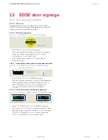
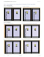
Страница 25: ...f door operator doors shall be provided with the message PUSH TO OPERATE on push side of door and PULL TO OPERATE on pull side of door 13 1 Low energy operator 13 1 1 Overview Signage and warnings are specified in ANSI BHMA A156 19 American National Standard for power assist and low energy power operated doors 13 1 2 All low energy doors 13 1 3 Knowing act switch used to initiate door operation 1 ...

Страница 26: ...86 010 DD0758 010 ACTIVATE SWITCH TO OPERATE DD0758 010 CAUTION DOOR AUTOMATIC DD0586 010 DD0758 010 ACTIVATE SWITCH TO OPERATE DD0758 010 Fig 13 2 3 Knowing act device Fig 13 2 4 Knowing act device opposite side Fig 13 2 6 Push Pull Pull Fig 13 2 5 Push Pull Push 50 12 CAUTION DOOR AUTOMATIC DD0586 010 DD0758 010 ACTIVATE SWITCH TO OPERATE DD0758 010 CAUTION DOOR AUTOMATIC DD0586 010 DD0758 010 A...

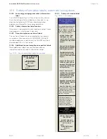
Страница 27: ...ave door repaired or serviced See Owner s manual or instructions for details on each of these and other safety items If you need a copy of the manual contact the manufacturer These minimum safety checks in addition to those in the Owner s Manual should be made each day and after any loss of electrical power 13 3 1 Low energy swinging door safety information label This AAADM label Fig 13 9 4 outlin...

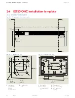
Страница 28: ...cap thickness 08 each End Cap End Cap Fig 14 1 2 Section view G G 1 Jambbracket 1 1 Jambbracket mountingholes 9 32 dia 1 Jambbracket mountingholes 9 32 dia For1 4 20fastener Fig 14 1 2 Section view H H 2 Headerfastener 3 Jambcutoutforwiring 4 Jambbracketcutout forwiring 2 Jamb cutoutfor wiring 2 3 4 3 4 2 1 2 3 4 3 4 1 1 4 H H Scale 1 2 ø1 3 8 Jamb header cover side 1 1 1 1 2 1 1 16 Jamb 6 4 1 1 1...

Страница 29: ...loor Pivot 1 2 Pivot E E Jamb Jamb D D Jamb Jamb Finished floor surface Finished floor surface 1 1 1 Pivot floormounted 1 Pivot floormounted 1 1 Fastener Reference Chapter 25 Install Floor Pivot 1 2 Pivot 2 1 4 Interior side 1 13 16 2 1 4 4 1 2 E E Scale 1 2 1 1 1 1 1 1 2 Jamb Finished floor surface D D Scale 1 2 Finished floor surface Jamb 1 2 1 3 3 4 3 7 16 Jamb D D Scale 1 2 Finished floor surf...

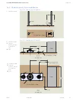
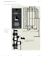
Страница 30: ...14 3 1 Program panel jamb cutout 2 3 4 1 1 2 3 1 4 1 5 8 R 1 8 TYP Finished floor 1 3 8 3 3 4 1 3 4 Program switch panel outline 1 3 16 1 2 3 3 3 2 X 36 drill Height as required C L If installing in a wood jamb or panel use a self threading flat head screw 1 Programpanelcable socket 2 RJ45connector 3 6 32x5 8 UCUTFHMS ...

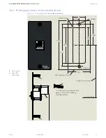
Страница 31: ... double doors Fig 14 4 1 RJ45 panel for dormakaba handheld 2 3 4 1 1 2 3 1 4 1 5 8 R 1 8 TYP Finished floor 1 3 8 3 3 4 1 3 4 RJ45 panel outline Jamb 3 1 3 16 2 3 3 2 X 36 drill Height as required C L If installing in a wood jamb or panel use a self threading flat head screw 2 RJ45connector 3 6 32x5 8 UCUTFHMS ...

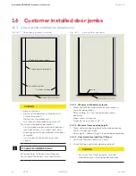
Страница 32: ...bs Refer to Para 14 1 for width between jambs dimension Measurement tolerance Width between jambs 1 8 0 16 1 2 Measure frame opening height 1 Measure frame opening height along door opening Minimum opening height Door height header height required door clearance 16 1 3 Check jamb level and floor flatness 1 Verify level between bottom of jambs 2 Check for floor high spots above jamb level Fig 16 1 ...

Страница 33: ...resolved prior to installing header and door Equal distance Center of door opening 16 2 2 Determine floor high spot in door swing arc 1 Place level on floor at bottom surface of jamb at door pivot side 2 Monitor level for any floor high spots above bottom of jambs in floor as level is moved through door swing arc CAUTION If level indicates floor high spots in door swing arc above bottom of jamb Co...

Страница 34: ...b mounting hole locations 2 Use clearance hole drill size for fastener being used 3 Drill hole 2 in jamb for wiring entering the header 16 3 Drill holes in jambs for header mounting and for wiring into header TIPS AND RECOMMENDATIONS Reference Chapter 14 ED50 OHC Installation Template Viewed from interior side of jamb Viewed from interior side of jamb LH jamb RH jamb Interior side of door Fig 16 3...

Страница 35: ...ut Reference Para 14 3 for cutout details 2 Insert RJ45 communication cable plug into socket on panel 3 Route program switch panel cable and RJ45 cable to top of jamb NOTICE Double doors Program switch panel installed on active door side jamb 2 3 1 3 4 16 6 2 RJ45 panel installation double doors 1 Install RJ45 panel in jamb cutout opposite program switch panel jamb Reference Para 14 4 for cutout d...

Страница 36: ...e ED50 OHC operator from mounting plate 1 Use 5 mm T handle hex key to loosen eight M6 SHCS securing operator to mounting plate SHCS must be free of mounting plate 2 Lift operator from mounting plate and set aside Fig 17 1 4 ED50 OHC mounting plate 1 M6x10SHCS 2 M6x20SHCS 3 Mountingplate 4 5mmThandlehexkey 1 2 3 4 1 1 2 2 3 1 M6x10SHCS 2 M6x20SHCS 3 Mountingplate Fig 17 1 2 ED50 operator fastener ...

Страница 37: ...HMS locations Fig 17 2 3 ED50 mounting plate location in right side of header 17 2 1 Install ED50 OHC mounting plate in right side of header TIPS AND RECOMMENDATIONS Refer to Chapter 5 for OHC door header configurations requiring ED50 operator installation on right hand side of header 6 1 1 Jamb bracket 5 OHC mounting plate 6 1 4 20 x 1 PFHMS 6 1 4 20 x 1 PFHMS screw pack DK4617 5 2 2 6 6 6 6 1 Fa...

Страница 38: ...header 4 1 1 3 3 3 3 1 1 1 2 Fig 17 3 1 OHC header ED50 operator mounting on left side Fig 17 3 2 ED50 mounting plate FHMS locations 2 5 6 6 6 6 1 1 17 3 1 Install ED50 OHC mounting plate in left side of header TIPS AND RECOMMENDATIONS Refer to Chapter 5 for OHC door header configurations requiring ED50 operator installation on left hand side of header 6 6 1 4 20 x 1 PFHMS screw pack DK4617 1 Fast...

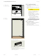
Страница 39: ...2 Low voltage terminal PCB 3 1 4 20 x 1 2 SBHCS 4 1 4 square nut installed in header track 5 OHC mounting plate installed on left Fig 17 4 2 Fasteners for Terminal PC board module ED50 operator on left 1 PCB holder assembly Terminal PCB DC4630 2 Low voltage terminal PCB 3 1 4 20 x 1 2 SBHCS 4 1 4 square nut installed in header track 6 OHC mounting plate installed on right TIPS AND RECOMMENDATIONS ...

Страница 40: ...is shipped with cutout and mounting holes for panic breakout switch Reference Figures 17 6 3 and 17 6 4 1 2 3 4 4 5 5 Fig 17 6 2 Wire harness 24 long 3 Wire harness 24 long 3 1 ED50 OHC double header outswing shown 2 Mounting plate LH ED50 OHC operator 3 TerminalPCboard 17 5 Double header Install ED50 OHC mounting plates and Terminal PC boards Fig 17 5 1 OHC double header ED50 OHC operator mountin...

Страница 41: ...ng plate 5 1 4 20 x 1 2 Phillips flat head undercut 6 Cutout and mounting holes 8 Header RH inswing 6 8 1 2 5 8 6 7 17 7 Install fixed stop outswing doors Fig 17 7 1 Fixed stop DK4638 020 1 Fixed stop 2 Mounting plate 3 8 x 5 8 FH thread forming screw 4 1 4 20 x 1 2 Phillips flat head undercut 1 2 4 4 3 17 7 1 Install fixed stop outswing doors 1 Install fixed stop assembly in header TIPS AND RECOM...

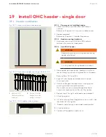
Страница 42: ...installation 1 Place header between jambs feeding wiring from jambs through jamb mounting brackets into header Refer to Para 19 2 and 19 3 2 Align left side header jamb bracket with jamb mounting holes 3 Install one flanged hex head screws through jamb mounting bracket into jamb material Use socket wrench to thread flanged hex head screws into jamb material Do not fully tighten 4 Repeat step 3 for...

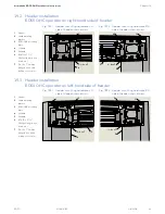
Страница 43: ...g 19 2 2 Header mounting hardware RH side of header internal view 19 2 Header installation ED50 OHC operator on right hand side of header 1 Header 2 Jambmounting bracket 3 ED50OHCmounting plate 4 LHjamb 5 RHjamb 6 14 10 x 2 1 2 Phillips flanged hex head zinc 7 1 4 14 x 1 Phillips flanged hex head drilling screw zinc 1 Header 2 Jambmounting bracket 3 ED50OHCmounting plate 4 LHjamb 5 RHjamb 6 14 10 ...

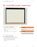
Страница 44: ...erence Chapter 16 customer installed door jambs 2 Header prepared Reference Para 17 5 double header preparation 20 2 Header installation 20 2 1 Reference installation chapter Refer to Chapter 19 Install OHC Header single door 1 Instructions are contained for header mounting with ED50 OHC operator on header right side ED50 OHC operator on header left side 2 Fasteners for securing header to jambs ar...

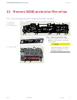
Страница 45: ... operator switching power supply heat transfer pads CAUTION Heat transfer pads must remain clean once protective film strips have been removed Fig 21 1 1 Operator protective film strips M6 fastener locations Fig 21 1 2 Operator protective film strip 2 2 2 2 1 1 1 1 3 3 1 M6x10SHCS 2 M6x20SHCS 3 Protectivefilmstrip Fig 21 1 3 Operator heat transfer pads 4 4 4 Heattransferpads 21 Remove ED50 protect...

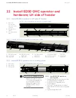
Страница 46: ...d 1 2 Outputshaft 1 3 ED50OHCoperator 115VACcable 2 Ribboncable 3 Lowvoltageterminal boardmodule 4 115Vacpower extensioncableDX4647 5 115Vacpowermodule 5 1 Mainpowercable 1 M6x10SHCS 2 M6x20SHCS 3 Mountingplate 22 2 1 Install ED50 OHC operator on mounting plate 1 Operator protective film strips must be removed Reference Chapter 21 2 Install ED50 OHC operator onto mounting plate 3 Use 5 mm T handle...

Страница 47: ...odule Velcro pad on header surface Fig 22 3 2 115 Vac power module installed 3 2 2 3 Fig 22 3 3 Cable connections 3 Low voltage terminal module 4 Main power extension cable DX4647 12 long 5 ED50 OHC operator power cable 6 Main power cable DK3772 010 7 Ribbon cable 8 Control board 22 3 2 Install cables 1 Install Main Power Extension cable one end into socket in 115 Vac power module the other end in...

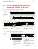
Страница 48: ...al boardmodule 4 115Vacpower extensioncableDX4647 5 115Vacpowermodule 5 1 Mainpowercable 23 1 Install ED50 operator in RH side of header DK3772 010 6 Groundlugkit DK4556 010 1 M6x10SHCS 2 M6x20SHCS 3 Mountingplate Fig 23 2 1 ED50 operator fastener locations 1 1 1 1 2 2 2 2 3 23 2 1 Install ED50 OHC operator on mounting plate 1 Operator protective film strips must be removed Reference Chapter 21 2 ...

Страница 49: ...long 5 ED50 OHC operator power cable 6 Main power cable DK3772 010 7 Ribbon cable 8 Control board 23 3 1 Install 115 Vac Power Module 1 Locate module in header between Low Voltage Terminal Module and jamb mounting bracket as shown in Fig 23 3 2 Note Main Power Extension Cable Fig 23 3 3 is 12 inches long 2 Install Velcro pad on bottom header surface 3 Install module on Velcro pad CAUTION Insure he...

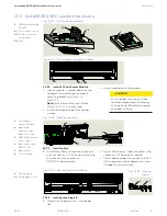
Страница 50: ... 5 1 6 8 1 3 Fig 24 1 3 Header LH door with ED50 OHC operator and hardware installed 24 1 1 Install ED50 OHC operators on mounting plate 1 Operator protective film strips must be removed Reference Chapter 21 2 Install two ED50 OHC operators onto onto their mounting plates 3 Use 5 mm T handle hex key to thread eight M6 SHCS into their mounting plate holes for each operator 4 Tighten all eight M6 SH...

Страница 51: ...able ground wire ring lug into self tapping screw 6 1 and thread screw into header slot Repeat for other ring lug 3 Coil up remaining length of cable and secure to header Fig 24 3 2 115 VAC Power cable DX3484 030 7 7 1 Fig 24 3 3 Ground lug kit DK4656 6 6 1 4 115Vacpower extensioncable DX4647 5 115Vacpowermodule 5 1 Mainpowercable DK3772 010 5 2 115Vacterminalblock 6 Groundlugkit DK4656 010 6 1 Se...

Страница 52: ... Phillips 14 FH wood screw Metal Phillips 14 FH sheet metal screw Concrete brick and mortar 1 4 concrete anchor for 14 screw or Tapcon screws 1 Select fasteners plated on Type of finished floor surface Floor material under finished floor surface if applicable 2 Concrete anchor Ref Fig 25 1 8 Insure that floor material can accommodate required anchor depth Anchor must be flush with floor surface 25...

Страница 53: ...ence Chapter 14 Installation Template for ED50 OHC drive axle dimensions from jamb Any issues with axle to floor pivot plumb must be resolved before proceeding 3 Remove M8 SHCS from drive axle 25 1 4 Install floor pivot 1 Mark floor with floor pivot hole locations for the two selected fasteners 2 Drill holes for fasteners 3 Secure floor pivot to floor with fasteners 2 3 Fig 25 1 7 Axle to floor pi...

Страница 54: ...ntenance 3 Terminate ground wire at ground lug TIPS AND RECOMMENDATIONS Install label in header with panelboard and circuit breaker number supplying 115 Vac to header TIGHTEN MAINS TERMINAL TO 5 7 in lb Use Copper Conductors ONLY Fig 26 1 1 115 Vac terminal torque and wire label 4 115Vacpower extensioncable DX4647 5 115Vacpowermodule 5 1 Mainpowercable DK3772 010 5 2 115Vacterminalblock 6 Groundlu...

Страница 55: ... OHC operator on RH side of header 6 5 1 5 4 5 2 Fig 26 1 5 115 Vac terminal block ED50 OHC operator on LH side of header Fig 26 1 7 115 Vac terminal block ED50 OHC double door header 4 115Vacpower extensioncable DX4647 5 115Vacpowermodule 5 1 Mainpowercable DK3772 010 5 2 115Vacterminalblock 6 Groundlugkit DK4656 010 5 1 5 4 6 4 5 5 2 ...

Страница 56: ...l switch location through jamb and into header 2 Carefully insert cable plug into socket on operator control board CAUTION Cable plug inserts vertically into operator socket NOTICE Double door installations program switch cable connects to active door operator Ref Chapter 33 27 1 2 Optional key switch panel wiring Reference Appendix D for key switch panel wiring diagrams 1 2 4 strand ribbon cable ...

Страница 57: ...anel back view 1 3 RJ45 port dormakaba handheld 2 RJ45 communication cable 10 DX4607 020 3 RJ 45 connector 4 Comm cable DX3485 double door synchronization 5 Controlboard 1 3 6 6 1 1 1 3 27 2 1 Install RJ45 communication cable 1 Route cable from RJ45 panel location through jamb and into header 2 Cable terminates at RJ45 port on inactive operator OHC operator control board NOTICE Double door install...

Страница 58: ...le doors Install axle extensions and arms at both ED50 OHC operators using steps in Para 28 1 1 28 1 1 Install 9 mm axle extension and OHC center hung arm 1 Insert conical spring and O ring onto M8 SHCS 2 Place 9 mm axle extension over ED50 axle 3 Install OHC arm over axle extension parallel to header as shown in Fig 28 1 1 and 28 1 2 4 Insert M8 SHCS through arm and axle extension 5 Using 5 mm T ...

Страница 59: ...et braking circuit plug position Operator braking circuit plug is positioned in its 3 pin socket for an outswing or inswing installation Braking circuit plug is factory installed in the two pins away from user interface the outswing position Fig 29 1 1 and Fig 29 1 2 WARNING Braking circuit will not work correctly if braking circuit plug is improperly positioned or if an incorrect plug is used Doo...

Страница 60: ...15 16 1219 to 1319 12 48 Parameter Tb value Door width measurement 29 2 2 Door width parameter Door width is set in increments of 100 mm 4 Measured width of 1000 mm 39 4 Tb value of 10 ED50 914 1219mm 36 48 29 2 4 Record door width 29 3 Reveal depth parameter rd Parameter Description Reference paragraph 2 rd Reveal depth Para 36 1 8 29 3 1 Reveal depth parameter center pivot door Reveal depth 0 rd...

Страница 61: ...erator 3 Spring tension adjustment 4 T handle hex key 5 mm Door width Inches 36 42 48 mm 914 1067 1219 Spring setting revolutions ED50 14 16 18 29 4 1 Spring tension setting revolutions CAUTION Any change to spring tension setting requires a new learning cycle Single door Para 31 9 Double door Para 32 2 TIPS AND RECOMMENDATIONS System checks spring tension during door installation partial learning...

Страница 62: ... until next desired parameter is displayed Step 8 Press left button for a minimum of 3 s to exit program mode Fig 29 5 1 dormakaba handheld 29 5 3 Configuration parameters Configuration parameters are set during initial startup Refer to Para 29 6 for configuration parameter detail 29 5 4 Driving parameters Driving parameters can be set once first commissioning has been completed Reference Appendix...

Страница 63: ...Reveal depth ED50 0 Reveal is set in increments of 10 mm 3 8 3 30 mm 1 1 8 Overhead concealed header Factory setting 3 Tb ED50 9 to 12 10 Door width 10 Door width is set in increments of 100 mm 4 10 1000 mm 39 4 Reference Para 29 2 measure door width 4 0 to 4 0 Door type 0 Single door 1 Double door Overlapping door with astragal Active door operator 2 Double door Overlapping door with astragal Pas...

Страница 64: ...2 Push arm with track wall mounting on approach opposite hinge side 3 Overhead concealed OHC RH Ref Para 29 6 4 OHC LH Ref Para 29 6 Factory setting 29 7 Set configuration parameters Fig 29 7 1 4 button keypad 2 digit display 3 Four button keypad 4 Two digit display 4 3 3s Reset 3s Quit 3s PRG 3s LEARN Fact Setup 3s 8s Step 7 Press Scroll to Tb parameter Step 8 Press Displays 10 factorysetting Ste...

Страница 65: ...letters and numbers will change if required to display correct orientation 2 Display scrolls 8 Device ID Ed 50 Firmware version format F x x x x 3 Program mode display Program mode 9 will be displayed indicating system requires further parameter settings TIPS AND RECOMMENDATIONS If pressing down button Para 29 8 5 does not result in desired display orientation return to Para 29 8 2 turn power butt...

Страница 66: ...sed position See Step 1 Arm must be blocked so arm cannot travel past this position Arm performs several movements and display shows a sequence of symbols Movements of arm must not be interrupted Display indicates arm is at 70 position Reference Fig 29 9 4 Step 4 If desired manually move door to 900 position for door installation TIPS AND RECOMMENDATIONS Arm installation Reference Chapter 28 Arm m...

Страница 67: ... arm at zero degree closed position Fig 29 9 4 Overhead arm at 70 degree position for door installation LH inswing example Fig 29 9 5 LH outswing Fig 29 9 6 RH outswing Header cover Header cover Header cover Fig 29 9 7 LH inswing Header cover Fig 29 9 8 RH inswing 29 9 3 Door overhead arm configurations ...

Страница 68: ...licable local building codes TIPS AND RECOMMENDATIONS Double door installation Reference Chapter 32 30 1 1 Conditions prior to installing door 1 Overhead arm rotated to 700 open position or greater 2 Floor pivot installed by customer CAUTION Jamb edge to floor pivot centerline distance 3 3 4 Reference Chapter 14 Installation Template Para 14 2 3 ED50 OHC operator axle to floor pivot plumb checked ...

Страница 69: ...verhead arm 1 Mortise top of door for overhead arm using dimensions referenced in Fig 30 2 2 and 30 2 3 2 Drill four holes for selected 1 4 hex head bolts Fig 30 2 2 Door mortise for overhead center hung arm LH inswing or RH outswing example Door mortise for arm 6 7 16 1 3 8 1 3 4 1 3 4 1 3 4 C L Arm installed in door reference view See Chapter 28 for arm installation into drive axle A A A No scal...

Страница 70: ... for bottom door pivot using dimensions referenced in Fig 30 3 2 and 30 3 3 2 Drill holes for selected 1 4 fasteners in the two slotted holes 30 3 2 Install bottom door pivot 1 Place bottom door pivot in mortise 2 Install fasteners and tighten 1 1 Door pivot release lever 30 4 Install floor pivot shaft bearing Fig 30 4 1 Floor pivot and bearing 1 Floor pivot 6 Bearing 30 4 1 Install floor pivot sh...

Страница 71: ...ertical and parallel to overhead arm 2 Move door under overhead arm Fig 30 5 2 30 5 3 Slide door onto bottom pivot 1 Slide bottom door pivot release lever over bottom pivot Fig 30 3 3 until door lowers onto bottom pivot bearing Fig 30 5 4 Bottom door pivot release lever holds door bottom pivot in place over bearing 2 Overhead arm mounting holes should be aligned with hex bolt clearance holes in ov...

Страница 72: ...g 30 5 6 2 Tighten four overhead arm hex bolts Fig 30 5 7 30 5 6 Check door plumb and level 1 Check door plumb and level Adjustment can be made by loosening fasteners in floor pivot slotted holes Para 30 3 and adjusting floor pivot as required 4 3 4 1 1 2 4 Door mortise 4 1 Clearance hole for hex bolts Bottom of door mortise Fig 30 5 6 Door mortise surface in contact with arm Fig 30 5 7 Overhead a...

Страница 73: ...gle is 110 Step 5 Press Momentarily press down button to continue learning cycle Door performs several movements and display shows a sequence of symbols Movements of door must not be interrupted Operator spring tension too low Display with small rotating o and an F during learn cycle indicates spring tension is too low Door will close 1 Increase spring tension Para 29 4 2 Restart learning cycle St...

Страница 74: ...at blade screwdriver required for adjustment 30 7 2 Setting door closing speed upon power failure 1 Turn ED50 power switch OFF 2 Manually open door to 90 angle and let it close 3 If door closes in less than 3 seconds turn potentiometer 1 4 turn CW and retry test TIPS AND RECOMMENDATIONS Total door closing time from full open to fully closed should not be less than 5 seconds Reference Chapter 36 AN...

Страница 75: ...eter 31 1 1 Set braking circuit plug position for each ED50 operator plated on door configuration Plug is positioned in its 3 pin socket for an outswing or inswing installation Braking circuit plug is factory installed in the two socket pins away from user interface the outswing position Fig 31 1 1 and Fig 31 1 2 WARNING Braking circuit will not work correctly if braking circuit plug is improperly...

Страница 76: ... 48 Parameter Tb value Door width measurement RH door LH door 31 2 2 Door width parameter Door width is set in increments of 100 mm 4 Measured width of 1000 mm 39 4 Tb value of 10 ED50 914 1219mm 36 48 31 2 4 Record width for each door 31 3 Reveal depth parameter rd Parameter Description Reference paragraph 2 rd Reveal depth Para 36 1 8 31 3 1 Reveal depth parameter center pivot door Reveal depth ...

Страница 77: ... LH side of header example 1 ED50 OHC header shown transparent 2 ED50 operator 3 Spring tension adjustment 4 T handle hex key 5 mm Door width Inches 36 42 48 mm 914 1067 1219 Spring setting revolutions ED50 14 16 18 31 4 1 Spring tension setting revolutions CAUTION Any change to spring tension setting requires a new learning cycle Chapter 32 TIPS AND RECOMMENDATIONS System checks spring tension du...

Страница 78: ...til next desired parameter is displayed Step 8 Press left button for a minimum of 3 s to exit program mode Fig 31 5 1 dormakaba handheld 31 5 3 Configuration parameters Configuration parameters are set during initial startup Refer to Para 31 6 for configuration parameter detail 31 5 4 Driving parameters Driving parameters can be set once first commissioning has been completed Reference Appendix A ...

Страница 79: ...d v2 1 4 OHC left hand v2 1 2 ED50 0 Reveal depth 0 Overhead concealed header Factory setting 3 Tb ED50 9 to 12 10 Door width 10 Door width is set in increments of 100mm 4 10 1000mm 39 4 Reference Para 31 3 4 0 to 4 0 Door type 0 Single door 1 Double door Overlapping door with astragal Active door operator 2 Double door Overlapping door with astragal Passive door operator 3 Double door Edgeless do...

Страница 80: ...0 starts flashing Step 10 Press Scroll to select parameter value 9 shown as example Step 11 Press Saves value entered Display stops flashing Step 12 Press Returns to door width parameter Exit program mode Step 13 Step 13 Press Exit program mode Display indicates ready for learning cycle 31 7 2 Set parameter Tb door width for each ED50 operator 31 7 3 Parameter dL door type TIPS AND RECOMMENDATIONS...

Страница 81: ...equired to display correct orientation 2 Display scrolls 8 Device ID Ed 50 Firmware version format F x x x x 3 Program mode display Program mode 9 will be displayed indicating system requires further parameter settings TIPS AND RECOMMENDATIONS If pressing down button Para 31 8 5 does not result in desired display orientation return to Para 29 8 2 turn power button off then back on to repeat steps ...

Страница 82: ...or closed position See Step 1 Arm must be blocked so arm cannot travel past this position Arm performs several movements and display shows a sequence of symbols Movements of arm must not be interrupted Display indicates arm is at 70 position Reference Fig 31 9 3 and 31 9 4 Step 4 If desired manually move door to 900 position for door installation TIPS AND RECOMMENDATIONS Arm installation Reference...

Страница 83: ...ructions Chapter 31 Fig 31 9 5 Double door inswing example arms rotated 70 degrees Fig 31 9 4 Double door LH arm inswing example Fig 31 9 3 Double door RH arm inswing example Fig 31 9 7 Outswing Fig 31 9 9 LH double egress Fig 31 9 8 Inswing Fig 31 9 10 RH inswing ...

Страница 84: ...s as well as any applicable local building codes Fig 32 1 2 Hanging doors 32 1 1 Conditions prior to installing doors 1 Overhead arms rotated to 700 open position or greater 2 Floor pivots installed by customer CAUTION Jamb edge to floor pivot centerline distance 3 3 4 Reference Chapter 14 Installation Template Para 14 2 3 ED50 OHC operator axle to floor pivot plumb checked for both doors Chapter ...

Страница 85: ...ngle is 110 Step 5 Press Momentarily press down button to continue learning cycle Door performs several movements and display shows a sequence of symbols Movements of door must not be interrupted Operator spring tension too low Display with small rotating o and an F during learn cycle indicates spring tension is too low Door will close 1 Increase spring tension Para 31 4 2 Restart learning cycle S...

Страница 86: ... screwdriver required for adjustment 32 3 2 Setting door closing speed upon power failure 1 Turn ED50 power switch OFF 2 Manually open door to 90 angle and let it close 3 If door closes in less than 3 seconds turn potentiometer 1 4 turn CW and retry test TIPS AND RECOMMENDATIONS Total door closing time from full open to fully closed should not be less than 5 seconds Reference Chapter 36 ANSI BHMA ...

Страница 87: ...t astragal Passive door operator Both doors open simultaneously Factory setting Step 1 Press Press and hold right button greater than 3 seconds to enter program mode AS parameter displayed Step 2 Press Scroll to dL parameter Step 3 Press Displays 00 factorysetting Step 4 Press 00 starts flashing Step 5 Press Scroll to select parameter value 1 as an example Step 6 Press Saves value entered Display ...

Страница 88: ... 2 1 Install communication cable 1 Set program switch to CLOSE 2 Install and route communication cable between the two operators 3 Connect communication cable to active and passive operator RJ45 horizontal jacks 4 Secure cable inside header 33 2 2 Test door operation 1 Set program switch to AUTO 2 Test double door operation Fig 38 3 4 Program switch 1 Program switch 3 position 1 TIPS AND RECOMMEND...

Страница 89: ...AUTION Clean any metal shavings from header Do not let metal shavings fall into the door area 39 1 2 Install fixed stop assembly in header TIPS AND RECOMMENDATIONS DK4646 kit part number for entire fixed stop assembly including backing plate 1 Align backing plate mounting holes with holes drilled in step 4 2 Install fixed stop assembly in header with fixed stop bumpers facing door 34 Install fixed...

Страница 90: ...ate fixed stop DC4644 7 Header LH outswing 9 Fixed stop mounting holes 9 32 dia Fig 34 1 8 Fixed stop installation RH outswing 1 Fixed stop 2 1 4 20 x 1 1 4 FHMS 3 3 4 flat washer 4 1 4 20 nut 6 Backing plate fixed stop DC4644 8 Header RH outswing 9 Fixed stop mounting holes 9 32 dia Fig 34 1 7 Fixed stop installation LH outswing Fig 34 1 6 Fixed stop mounting holes RH outswing 2 3 4 1 6 8 9 8 2 3...

Страница 91: ...1 System Accessories for terminal board interfaces 1 Secure all accessory wiring in header 35 1 2 Panic breakout switch wiring Reference Para 17 6 for switch installation on inswing doors 1 Breakout switch wires terminate at X6 4 and 4a on ED50 terminal board Remove jumper between 4 and 4a Fig 35 1 2 Reference Para 11 3 ED50 terminal board interface 35 1 3 Test system accessories Test functionalit...

Страница 92: ...allremainatthefully openedpositionfornotlessthan3s hS Reference ED50service manualfor parameter detail Supportformanualmodein doorclosedposition 4 5 Doorsshallopen Withamanualforcenottoexceed15lbf to releasealatchifequippedwithalatch T osetadoorinmotion30lbf T ofullyopenthedoor15lbf Forcesshallbemeasured1 fromlatchedge ofdoor hA Adjustment dooractivation angle hF Powerassistfunction Fo Static forc...

Страница 93: ...lcontinueatthesamerateasbackcheckspeed Backcheckoccurringatapointbetweenpositionsshalluselowestsetting 36 1 4 Other door weights and widths Closing time T D W 188 D Width of door in inches W Weight of door in pounds T Closing time to latch check in seconds 37 Install door signage header cover 37 1 Install door signage 37 1 1 Install door signage plated on type of door installation Install applicab...

Страница 94: ...erator control unit replacement If the control unit is replaced the container module is removed from the old control unit and inserted into the new control unit The new control unit synchronizes with the container module and all upgrade card functions are available 38 2 4 Inserting an upgrade card that has already been activated Rapidly flashing yellow LED on upgrade card indicates card is rejecte...

Страница 95: ...de card slot 4 6 Card function is copied to control module upgrade card is then invalidated Yellow LED indicates procedure is complete 6 1 3 Remove upgrade card from upgrade card slot 4 Reinsert container module into upgrade card slot Control unit recognizes container module container module stores new functions Green LED slowly flashes on and off indicating successful operation New card functions...

Страница 96: ...ther liquids CAUTION No water or other liquids must be sprayed or spilled on ED50 OHC header Table 39 1 1 Operator environmental requirements Fig 39 1 1 ED50 OHC header and LH door Ambient temperature 5 to 122 F Suitable for dry rooms only Relative air humidity 93 maximum non condensing 39 2 Operator status LEDs Fig 39 2 1 Operator status LEDs 39 2 1 Operator status LEDs Header cover must be opene...

Страница 97: ... 8 long custom 3 2 Conical spring 3 3 O Ring 39 3 1 Check overhead arm and connection to drive axle 1 Remove door s Door s must be removed to check overhead arm connection to drive axle and bottom door pivot Reference Paragraph 30 single door or 32 double door for door installation 2 Check arm and extension hardware for wear and tear 3 Check tightness of M8 SHCS CAUTION Use torque wrench with 5 mm...

Страница 98: ...ft hand v2 1 2 ED50 3 to 50 0 Reveal depth 0 Reveal is set in increments of 10 mm 3 8 3 30 mm 1 1 8 ED50 OHC overhead arm is on center with door 0 factory setting Parameter and value range factory setting bold Parameter description 3 Tb ED50 7 to 15 10 Door width 10 Door width is set in increments of 100 mm 4 10 1000 mm 39 4 ED50 700 1219mm 28 48 4 0 to 4 0 Door type 0 Single door 1 Double door Ov...

Страница 99: ...Sr Status relay function terminal block X7 Driving parameters Description 28 bE Input 4 4a and X3 1G 24V locking device output configuration 29 CC Cycle counter number displayed 10000 30 EC Delete error log 31 CS Reset service interval display yellow LED 32 SL Factory setting level Fact Setup button 33 OA Opening angle set during learning cycle 34 hd Door closer mode automatic or manual 35 hA Powe...

Страница 100: ...of 5 seconds 4 In low energy mode a minimum hold open time of 5 seconds is required 5 Hold open time can be re triggered If hold open times greater than 30 seconds are desired professional upgrade card extends maximum hold open time to 180 seconds 7 0 30 s 5 0 180 s Night bank hold open time 1 Night bank key switch hold open time is set using this parameter 2 Night bank Hold open time starts once ...

Страница 101: ...ion drive 13 0 1 0 0 Safety sensor on swing side is active during an initialization drive after a power on reset 1 1 With SP set to 1 operator will disregard swing side safety sensor during initialization drive v1 9 After a power on reset operator starts an initialization drive at slow speed The initialization drive cannot be completed if safety sensor on hinge side is or has been triggered Delaye...

Страница 102: ... 4 10 lbf 1 35 10 Static force in closing direction 1 Static force in closing direction basic parameter for wind load control Static force on door closing edge can be changed using this parameter 2 Internal monitoring system checks if parameter setting is admissible If setting exceeds admissible value the setting is alternately displayed with the permissible value 3 After parameter set verify sett...

Страница 103: ... 0 1 In event of power failure or if operator is deliberately switched off EPS will automatically switch to last known position when power returns 2 Important The time at which power returns might not be during business hours and may affect insurance compliant door locking requirements 1 1 In event of power failure or if operator is deliberately switched off EPS will automatically switched to OFF ...

Страница 104: ...e output terminal X3 1G 24V is independent of Input X6 4 4a 1 1 Locking device output terminal X3 1G 24V is turned on as soon as contact at X6 4 4a is opened v1 9 2 Terminal X3 1G 24V output is on for as long as contact at X6 4 4a is open motor lock with a 100 duty factor is required 3 This function is not available for DCW motor locks Cycle counter 1 Total number of opening and closing cycles dis...

Страница 105: ... changed during learning cycle 3 Due to installation and parameter tolerances display value may not match actual door position 33 0 110 Door closer mode 34 0 1 1 0 1 Automatic mode This mode is applicable whenever door is mainly opened automatically and where motion detectors are installed 2 Mode is optimized for high frequency use 3 Full energy upgrade card provides for higher door opening and cl...

Страница 106: ...nergy mode 0 3 0 0 Upgrade card not installed function not available 1 Upgrade card installed function not activated 2 Upgrade card installed function activated 3 Upgrade card has been removed function no longer available Upgrade card fire protection 1 Once upgrade card installed parameter value will automatically change to 2 2 Following activation drive may be used as a electrically controlled ho...

Страница 107: ...3 0 Upgrade card barrier free toilet 1 Once upgrade card installed parameter value will automatically change to 1 2 Function must be activated by changing parameter F7 to 2 3 Operator power reset is required turn power switch off wait 10 s and turn power back on 4 Upgrade card assigns inputs and outputs of the control unit with functions which are required for this application 43 0 1 2 3 0 Upgrade...

Страница 108: ...manually moving door in closed direction 2 A manual release button is not required 0 1 Hold open release by manually moving door in closed direction is deactivated 2 A manual release button is required Castor angle for double doors Active door with astragal angle active door must open before passive door opens 51 0 30 30 Hinge clearance 1 Clearance between hinges is critical for the calculated doo...

Страница 109: ...rator Red LED adjacent to operator power switch displays blinking codes for 1 Certain ln information 2 E status codes Para B 2 CAUTION Always analyze and remove cause for error before resetting error message Troubleshooting charts Para B 3 4 are intended as a guide for diagnosing errors TIPS AND RECOMMENDATIONS Para B 2 Red LED Status Codes Para B 3 Information Codes Para B 4 Error Codes 1 RedLED ...

Страница 110: ...ing 5 times E51 E52 E53 Incrementalencodererror Flashing 6 times E62 Doubledooroperation 2ndsystem hasincompatiblefirmwareversion Flashing 6 times E63 Doubledooroperation 2ndsystem hasincompatiblefireprotection setting Flashing 7 times E71 Systemerror1 test second shutdownoption Flashing 7 times E72 Systemerror2 test current measuringcircuit Flashing 7 times E73 Systemerror3 test brakingcircuit Fl...

Страница 111: ...n reinstalled or is defective 1 Installed Upgrade card may not be removed from operator 2 If more than one upgrade card is installed the first card installed becomes the container module Reference chapter 18 for Upgrade card installation The container module must be installed last after all other Upgrade cards are installed 3 If container module defective first upgrade card container module must b...

Страница 112: ...If this is not possible reactivate the drive Reactivation can be done by Switching program switch to Close off Pressing both 4 button keypad left and right buttons 3s B 4 Troubleshooting chart E code No Display Red LED Description Troubleshooting error codes 1 E 02 Flashing 2 x Locking device error Operator is attempting to open or close a locking device with feedback or a DCW locking device An er...

Страница 113: ...lashing 6 x Incompatible fire protection setting double door system 1 For double door systems the Upgrade card fire protection must be installed in both control units 11 E 71 Flashing 7 x System error 1 2nd shutdown option 1 In order to reliably switch off the drive unit several switching elements are used and their functions are tested periodically 2 If the function test always results in the err...

Страница 114: ... key functions 1 OFF ON switches Handheld on or off 2 Function keys F1 F3 trigger functions shown in bottom line of display e g RPT for repeat UP and DOWN to switch lines UpDoLd for file up and download CHANGE to change values OPEN to trigger opening pulses 3 Arrow keys allow navigation within the display Use left arrow to get back to previous screen 4 ENTER selects individual menu items and confi...

Страница 115: ...trigger pulse with door closed 14 Lock delay 3 Delayed opening time for locking mechanism 0 3 100 msec 15 Unlock force 0 Preload prior to unlocking 0 9 12 Test PR module 0 Test off 1 Test once every 24 hrs 23 Program switch Internal External DCW 24 PGS power up DCW Last Off 25 PGS delay Off On 26 Daytime unlock Off On Locking device remains permanently unlocked while door is in closed position 27 ...

Страница 116: ...ce open 60 Static force in opening direction wind load control 20 150 N 18 Limit force close 60 Static force in closing direction wind load control 20 150 N 7 Hold open time 5 Hold open time automatic mode 0 180 s ED50 8 Nurse bed function 10 Hold open time nurse bed function 0 180 s Parameter and default Description Selections 5 Offenhaltez man 1 Hold open time manual mode 0 30 s 10 Wall blanking...

Страница 117: ...ked active fehlt 42 Nurse Bed func locked Upgrade card professional unlocked active fehlt 38 Fire protection r o locked Upgrade card fire protection unlocked active fehlt Parameter and default Description Selection 39 Full energy r o locked Upgrade card full energy unlocked active fehlt 44 DCW r o locked Upgrade card DCW unlocked active fehlt 43 Disabled restr r o Upgrade card Barrier free toilet ...

Страница 118: ...nterval Enter maintenance interval 6 24 months 12 Service cycle interval Enter number of opening and closing cycles until next maintenance 200 1000 1000 200 Parameter name Description Setting Wartungs datum Maintenance data x x y y month year Cycles total r o Displays total opening and closing cycles Zyklen max h r o Displays maximum number of cycles in one hour h Zyklen h r o Displays number of c...

Страница 119: ... 6 Press F3 to select Änd Amendments 7 Scroll down SPRACHEN menu to Englisch Press once to highlight Englisch 8 Press ENTER to select Englisch Fig C 6 1 dormakaba handheld Fig C 6 9 Englisch highlighted Fig C 6 10 SETTINGS menu TIPS AND RECOMMENDATIONS Handheld programmer will retain English setting when unit is turned off Change to English only required the first time the programmer is turned on ...

Страница 120: ...utton Fig C 7 3 Enter Handheld user code 1 Connect Handheld to COM 1 port Para D 1 and power on Handheld will boot up and display main menu C 7 1 Firmware update procedure CAUTION For all firmware changes set program switch to CLOSE and allow door to close completely before any updates are made 2 With Communication highlighted press ENTER 3 Enter Handheld user code and press ENTER 1 1 ...

Страница 121: ...ig C 7 5 Select Firmware upload 5 Use Up and Down arrows to select Firmware upload and press ENTER Fig C 7 6 Select Firmware version 6 Use Up and Down arrows to select firmware version and press ENTER Fig C7 7 Start transmission 7 Press any key to start firmware transmission Fig C7 8 Firmware uploading Fig C 7 9 Complete firmware update 9 Press any key to complete firmware update ...

Страница 122: ...r 27 for RJ45 cable connection RED WHT BLK GRN B L K ORG 57 57a X10 X8 X4 X5 X6 15 17 11 3 1 13 3 1 42 3 3 1 1 41 35 33 32 3 30 3 34 31 1 6 3 1 4 4a 99 98 97 3 B A 1 3 43 64 63 62 1G 3 X9 X1 X7 X3 24 0V 0V 24 Swing side 0V 0V Test Signal Approach side Signal Test 24 0V Feedback contact 0V 0V Door status 35 33 32 3 30 3 34 31 X1 0V 0V Off Automatic Exit Only Permanent Open WHT GRN ORG RED BLK 22 AW...

Страница 123: ...11 3 1 13 3 1 42 3 3 1 1 41 35 33 32 3 30 3 34 31 1 6 3 1 4 4a 99 98 97 3 B A 1 3 43 64 63 62 1G 3 X9 X1 X7 X3 24 0V 0V 24 Swing side 0V 0V Test Signal Approach side Signal Test 24 0V Feedback contact 0V 0V Door status 35 33 32 3 30 3 34 31 X1 0V 0V Off Automatic Exit Only Permanent Open WHT GRN RED BLK 22 AWG stranded 7 x 30 Length 80 inches AUTO CLOSE OPEN Fig D2 2 Key switch panel wiring diagra...

Страница 124: ...www dormakaba com dormakaba USA Inc 1 Dorma Drive Drawer AC Reamstown PA 17567 USA T 717 336 3881 F 717 336 2106 ...

Отзывы: