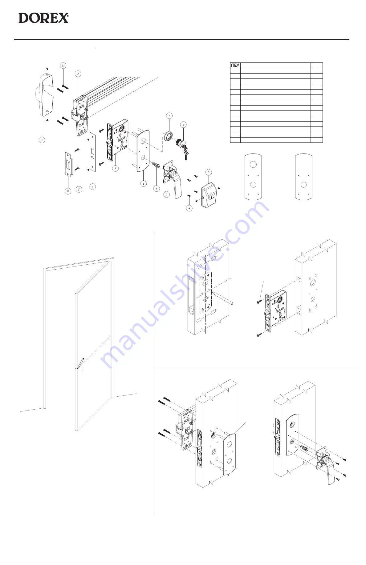
1 FULL PLATE
1
2 SPINDLE
1
3 PULL HANDLE ASSEMBLY
1
4 SCREW
1
5 COVER
1
6 CYLINDER
1
7 CYLINDER GUARD
1
8 MORTISE CASE
9 ARMOR FRONT
10 SCREW
11 STRIKE
12 DEVICE COVER
13 MOUNTING SCREW
14 EXIT DEVICE
DESCRIPTION
QTY
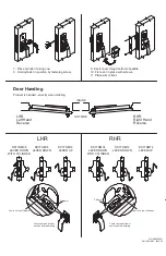
RHR shown
(LHR opposite)
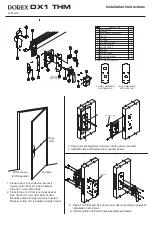
1. Prepare door for exit device. See exit
device instructions for holes, backset
(line X-X), and center lines.
2. Transfer line X-X from inner (exit device)
side of door to outer (trim side) of door.
Be extra careful if edge of door is beveled.
Make sure line X-X is parallel to edge of door.
L
C
X
X
Hinge
Side
Outside
3. Align and stick template onto door, mark position and drill.
4. Install Mortise and fasten with mounting screws.
Mounting Screws
5. Place Full Plate and Exit device onto door according to product's
installation instructions.
6. Install spindle and Pull Handle Assembly and fasten.
Full Plate
L
C
X
X
For Full Plate
selection see
figure on the right
1
1
1
1
1
Note:8~14 are sold separately.
4
4
For DX1THM08RHR
DX1THM08LHR
For DX1THM14RHR
DX1THM14LHR
DX1 THM
Installation Instructions
Pull Latch


