INSTALLATION, USE AND MAINTENANCE
GBA-GBP-CBE-MBE SERIES
41
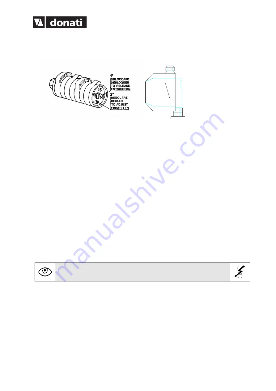
4.3.8.1 Commissioning of the rotation limit switch
Operate as follows:
Function of the contacts:
SQ5A = RIGHT rotation service limit switch
SQ6A = LEFT rotation service limit switch
SQ5B = RIGHT rotation emergency limit switch
SQ6B = LEFT rotation emergency limit switch
Adjusting the contacts:
1. Adjust the cam related to the SQ5B emergency contact immediately after the operation on the Adjust
the cam related to the SQ5A contact to limit the rotation to the RIGHT, as required. SQ5A contact.
2. Adjust the cam related to the SQ6A contact to limit the rotation to the LEFT, as required. Adjust the
cam related to the SQ6B emergency contact immediately after the operation on the SQ6A contact.
Note: the operation on the emergency limit switch contacts blocks the functioning of the whole machine. To
activate an emergency operation, once the cause is identified, it is necessary to operate on the limit switch,
releasing momentarily the cam of the contact in question.
Get out of the anomalous position with the opposite control to that of the operation.
Restore the original position of the contacts.
4.3.8.2 Assembly of the electric system with isolating switch for GBA-CBE pillar-mounted
cranes
For the assembly of the electric system proceed as follows:
1. Extract the cable trolleys or cable sliders and the other components from any packing.
2. Insert the power cable
1
in the cable sliders
2
, in the case of the channel girger (fig. 59), or in the cable
trolleys
3
in the case of the girder arm (fig. 60), so as to form a series of festoons of equal width. Clamp
the cables with the relative screws or seatings.
3. Insert the sleds, or slides, in the relative sliding housings (channel-girder or double-
T“girder”) - (fig.
61).
4. Assemble the isolator switch as in fig. 67, assembling the components 1-2-3-4-5.
5. Position the isolating switch in the hole in the pillar, connecting the relative electric cables, finishing
the
6. assembly with the application of the yellow frame and of the red knob as in fig. 68.
Содержание CBE Series
Страница 2: ......
Страница 16: ...INSTALLATION USE AND MAINTENANCE GBA GBP CBE MBE SERIES 12 T Version Manual Underbraced version...
Страница 17: ...INSTALLATION USE AND MAINTENANCE GBA GBP CBE MBE SERIES 13 H Version Manual overbraced version...
Страница 19: ...INSTALLATION USE AND MAINTENANCE GBA GBP CBE MBE SERIES 15 H Version Manual overbraced version...
Страница 79: ......

