7
Donaldson Company, Inc.
Fan With Inlet Spool Piece Mounted to
Clean Air Outlet Without Weld Nuts
The following instructions are for a fan with an integrated
inlet spool piece being mounted on collectors that do
NOT have weld-nuts on the clean air outlet.
1. Apply the sealer, furnished in the installation
hardware kit, around clean air outlet opening of the
collector. Sealer should be applied in a Figure 8 type
pattern around each bolt hole so that inlet is sealed
from both the outside and the inside of the bolt hole.
2. Remove the inlet spool from fan. Retain the hardware
to for use when fan is reattached to the spool in
Step 5.
3. Position the inlet spool piece onto the collector
surface. Align mounting holes.
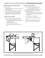
4. Bolt the inlet spool piece to the collector clean
air outlet by inserting supplied hardware. Reach
through to secure the nuts on the inside of the clean
air plenum. Apply supplied Loctite on nut.
Fan With Inlet Spool Piece Mounted to
Clean Air Outlet With Weld Nuts
The following instructions are for a fan with an integrated
inlet spool piece being mounted on collectors that have
weld-nuts on the clean air outlet.
1. Apply the sealer, furnished in the installation
hardware kit, around clean air outlet opening of the
collector. Sealer should be applied in a Figure 8 type
pattern around each bolt hole so that inlet is sealed
from both the outside and the inside of the bolt hole.
2. Position TBI fan and spool assembly onto the
collector surface. Align mounting holes.
3. Bolt the TBI fan and spool assembly to the collector
clean air outlet by inserting hardware supplied
through the inlet spool piece and into the weld nut
in the clean air plenum. Be sure to position the
discharge to be free of obstructions and locate so
that the motor’s electrical box will be positioned for
wiring convenience.
4. Inspect the installation prior to starting the fan.
Check for any loose items or debris that could be
drawn into the fan or dislodged by the air discharged
from the fan outlet. Check the interior of the fan as
well. Turn the wheel by hand to check for binding.
5. Complete the electrical connections in accordance
with NEC code and state and local codes. “Bump”
the starter to make sure the motor is rotating in
the proper direction. (Standard TBIs are clockwise
rotation as viewed from the motor endbell.)
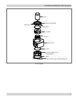
spool
apply loctite to
threads and face
of nut
cabinet (reference)
Steps 3-4
Step 2

