Downflo II, Models DFT 2-4 and DFT 3-6
29
setpoint. The auxiliary relay can also be used to
activate visual or audible alarms provided by
others.
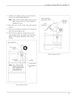
6. Thirty-five feet of plastic tubing is supplied with
the control and must be cut in two sections.
Connect one section of tubing from the control
enclosure
s high-pressure port to the pressure
tap on the dirty-air plenum. Connect the
remaining section of tubing from the control
enclosure
s low-pressure port to the pressure
tap on the clean-air plenum. Additional tubing
can be ordered from your representative.
7. Place the program wire on the solid-state timer
board pin to match the number of solenoid-
valve connections used.
8. Apply power to the control. Set the high- and
low-pressure setpoints to start and stop the
cleaning process. Set the alarm setpoint to
activate the alarm display. See Control
Calibration section on page 30.
47
WMHIZMI[
EYXSXVER
&/8
'
6
9
0
0
0
'
'
'
6 6
6
6
6 6
'
'
=
(
.
9
6
6
'
6
8
6
6
6%
9
9
6%
6%
6%
%((6)77
7;
'
6 6 6
PS[
'4
(
(
'6
'6
8&
1SHI
WPEZI
EPEVQ
6
5
.
LMPS
GSRXVSP
EPEVQSV
EY\MPMEV]
.
.
2'
2'
TVSK
HMWEFPI
EPEVQ
VIWIX
6 6 6 6
6 6 6 6
6
6
'
'
8&
.
MRQQ
0
0
8&
:
MRTYX
;
;
;
: : :
94
(3;2
'4
'4
'4
9
9
'
LMKL
%PEVQ
'
6
6
6
6
6
'PIERMRK
%PEVQ
'4
9
'
5
5
5
5
5
[K
QQ[K
6
6
6
6
6
5 5
6
6
6
6
0)(
0)(
0)(
0)(
6 6
5
6
5
6
6
6
6
' ' '
:6
9
'322
6
6
6
'
:6
*
( ( ' '
8
%'
4.
EPEVQ
HMWEFPI
YRMXW
[K
SV
HE4%
ZSPXEKINYQTIVW
TS[IVGSRRIGXMSR
WIRWSV
SYX
Delta P Control Printed Circuit Board
Содержание Downflo II DFT 2-4
Страница 45: ...Downflo II Models DFT 2 4 and DFT 3 6 45 e t a D d e m r o f r e P e c i v r e S s e t o N Service Notes...
Страница 46: ......
Страница 47: ......


