background image

FAULT FINDING AND REPAIR

4-8

20509 Issue 7 Jan 2018

(9) Tails forming on printed drops - surface speed too high - reduce 

intensity (

see page 2-17

). 


PRINT HEAD

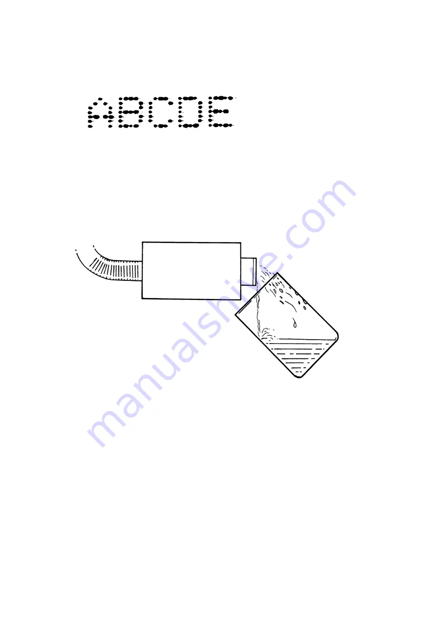
Bleeding the Print Head

The printer should be switched on, with the Pump Inhibit switch in position


1 and the ink system properly primed.

(1) Close the valve on the print head by turning the knob fully clockwise. 


(2) Place a 500 ml beaker under the nozzle plate. A suitable beaker is 

supplied in the tool kit.

(3) Carefully loosen the nozzle plate fixing screws just sufficiently for air 

and ink to escape.

(4) Slowly open the print head valve by turning the knob counter-

clockwise and allow air and ink to escape into the beaker.  Continue 
bleeding the print head until approximately 250ml of ink has been 
collected.

(5) Close the print head valve and tighten the nozzle plate screws.  Wash 

surplus ink from the nozzle plate and dry with lintfree tissue.

(6) Open the print head valve.  Purge the head (

see page 3-4

).  Check the 

print head for leaks.

TP3048-1

TP3370-1

Содержание Macrojet 2

Страница 1: ...Domino Macrojet 2 Product Manual ...

Страница 2: ... 2 20509 Issue 7 Jan 2018 THIS PAGE INTENTIONALLY LEFT BLANK ...

Страница 3: ...t 1 Health and Safety All rights reserved No part of this publication may be reproduced stored on a retrieval system or transmitted in any form or by any means electronic mechanical photocopying recording or otherwise without the prior permission of Domino Printing Sciences plc Domino Printing Sciences plc has a policy of continuous product improvement the Company therefore reserves the right to m...

Страница 4: ...r L21548 The object of the declaration described above is in conformity with the relevant Union harmonisation legislation 2014 35 EU Low Voltage Directive 2014 30 EU EMC Directive EN 60950 1 2006 A2 2013 Information technology equipment Safety Part 1 General requirements EN 61000 6 2 2005 Electromagnetic compatibility EMC Part 6 2 Generic standards Immunity for industrial environments EN 61000 6 4...

Страница 5: ...20509 Issue 7 Jan 2018 5 ...

Страница 6: ...ironment This equipment generates uses and can radiate radio frequency energy and if not installed and used in accordance with the instruction manual may cause harmful interference to radio communications Operation of this equipment in a residential area is likely to cause harmful interference in which case the user will be required to correct the interference at his own expense Any changes or mod...

Страница 7: ...20509 Issue 7 Jan 2018 7 CONTENTS PART 1 HEALTH AND SAFETY PART 2 DESCRIPTION PART 3 MAINTENANCE PROCEDURES PART 4 FAULT FINDING AND REPAIR PART A INSTALLATION ...

Страница 8: ...Feb 91 Following pages amended to Issue 2 0 July 91 Preface 7 1 4 1 5 3 32 4 11 4 13 4 17 5 17 A2 A20 All pages at Issue 3 April 92 All pages at Issue 4 July 95 All pages at Issue 5 April 99 All pages at Issue 6 July 2011 All pages at Issue 7 Changes to voltage regulator Jan 2018 ...

Страница 9: ...20509 Issue 7 Jan 2018 1 1 PART 1 HEALTH AND SAFETY CONTENTS Page Introduction 1 3 Basic Requirements 1 3 Storage 1 4 Fire Risk 1 4 Spillages and Disposal 1 5 ...

Страница 10: ...HEALTH AND SAFETY 1 2 20509 Issue 7 Jan 2018 THIS PAGE INTENTIONALLY LEFT BLANK ...

Страница 11: ...the mouth must be avoided Therefore eating drinking or smoking or any personal habits or actions which may transfer ink to the mouth must be avoided Contact with the eyes must be avoided Suitable eye protection must always be worn whenever there is any risk of splashing or misting If ink does get into the eyes first aid treatment is to flood the affected eye for 15 minutes with saline solution or ...

Страница 12: ... not use metal scrapers to remove it as they can produce sparks If dry Nitro cellulose based ink ignites it will generate its own oxygen and can only be extinguished by lowering the temperature with water If a Nitro cellulose fire occurs ENSURE THAT THE ELECTRICAL POWER IS IMMEDIATELY REMOVED FROM THE PRINTER BEFORE water is used to extinguish the fire Fire risk is a most important consideration w...

Страница 13: ... soon as possible with the appropriate solvent materials and with regard to the safety of personnel Care must be taken to prevent spillages or residue from cleaning up entering drains or sewage systems Inks and associated fluids are materials which conduct electricity Therefore power to the printer must be switched off while spillages inside the printer cabinet are being cleaned up Printing inks a...

Страница 14: ...HEALTH AND SAFETY 1 6 20509 Issue 7 Jan 2018 THIS PAGE INTENTIONALLY LEFT BLANK ...

Страница 15: ...Head 2 7 Control Cabinet 2 11 Ink System 2 12 General 2 12 Ink System 2 14 Electronic System 2 16 General 2 16 Controls and Indicators 2 17 Universal Serial Interface PCB 2 18 Solenoid Driver PCB 2 18 Low Voltage Power Supply PCB 2 18 Motherboard 2 20 Product Detector 2 20 Shaft Encoder Optional 2 20 External Connections 2 22 Product Detector and Shaft Encoder Connectors 5 pin AXR 2 22 Power Conne...

Страница 16: ...DESCRIPTION 2 2 20509 Issue 7 Jan 2018 This page intentionally left blank ...

Страница 17: ...DESCRIPTION 20509 Issue 7 Jan 2018 2 3 Macrojet 2 Large Character Printer TP1006_1 Ink Box Control Cabinet Print Head ...

Страница 18: ...external connections are grouped on a panel at the rear The product detector is mounted on the line and senses the product as it approaches the print head There are three optional types two are infra red beams and a third works by metal detection Ink is supplied in a disposable 5 litre bag in box ink container connected to the printer by a Quick Connect Disconnect QCD connector Messages to be prin...

Страница 19: ...5 or 16x10 matrix Character height 8mm 5x5 matrix 12 and 32 only 12 16 20 7 x 5 matrix 12mm Tray Coder 32mm 16 x 10 matrix or 2 lines 12mm 7x5 matrix 50mm 16 x 10 matrix or 2 lines 20mm 7x5 matrix Maximum print speed 100 metres second at 12 5mm Character width ch Messages Up to 40 messages of up to 200 characters length Dimensions Width 394mm 15 51 Depth 443mm 17 44 Height 282mm 11 1 Weight 24 5kg...

Страница 20: ...single phase with ground Power 300VA Supply frequency 50 60Hz Power switch 2A 220 260V 4A 110 150V Product Detector 12V 100mA dc supply to sensor 5 pin AXR connector Shaft Encoder print rate control suitable for open collectors or TTL encoders Encoder power supply link selectable 5V or 12V 5 pin AXR connector Data Interface RS232 or 20mA current loop 75 19 200 Baud selectable One output via change...

Страница 21: ...d successive strokes containing different combinations of ink drops build up the character in the form of a dot matrix This is best understood by studying the illustration below A dot matrix is specified by the number of dots in a stroke and the number of strokes making up a single character for example the illustration shows a 7x5 matrix The Macrojet print head has at the front a nozzle plate wit...

Страница 22: ...s mounted at right angles to the print surface at a distance of 3 to 5mm for best print quality At distances outside these limits print quality will be reduced Macrojet 2 has a number of print head and print options The print options are shown in the diagrams see page 2 9 and page 2 10 A 7 drop head will print only the single line options A 16 drop head is required to print the twinline and large ...

Страница 23: ...ssue 7 Jan 2018 2 9 TP1410_1 Single line 7 x 5 matrix Standard Character Printing Styles TP1412_1 TP1413_1 TP1414_1 Twin line 7 x 5 matrix Single line 16 x 10 matrix Single line 16 x 10 and 7 x 5 matrix top or bottom line ...

Страница 24: ...8 TP1415_1 Single line 5 x 5 matrix Optional Character Printing Styles TP1417_1 TP1418_1 TP1419_1 Twin line 5 x 5 matrix Single line 5 x 5 and 7 x 5 matrix Single line 16 x 10 with single line 7 x 5 and single line 5 x 5 top or bottom line ...

Страница 25: ...onnectors is fitted into the rear of the cabinet The panel is also fitted with a fan that prevents an accumulation of fumes in the cabinet The air is exhausted out of holes in the base under the transformer The ink and electronics systems occupy separate halves of the base and a bulkhead formed in the cover drops between them Removing four screws and lifting the cover provides access to the whole ...

Страница 26: ... in ink from the ink supply container and supplies it under pressure to the print head The system is governed by switches which control the ink pressure and detect when the ink container is empty Ink System Components TP1385_2 Vent Bleed Valve Priming Port Ink Manifold Accumulator ...

Страница 27: ...2018 2 13 Ink System Diagram M Accumulator Bleed Valve Vent Print Head Valve Print Head Main Cabinet Ink Container QCD Connector Vacuum Switch Filter Spring NRV Print Head Manifold Solenoids Pressure Switch Choke Bleed Reservoir NRV ...

Страница 28: ...he mounting flange on the steel frame The diaphragm is shaped to contain a volume of air The mounting flange is sealed and the only access into the diaphragm is an air valve provided for maintenance purposes As ink is pumped into the accumulator it compresses the air sealed inside the diaphragm When the ink is pressurised to 7psi 0 48 Bar the pressure switch trips and switches the pump off The pla...

Страница 29: ...20509 Issue 7 Jan 2018 2 15 Electronics Components TP1390_2 Power Transformer Motherboard Front Panel Assembly Low Voltage Power Supply PCB Universal Serial Interface PCB Solenoid Driver PCB Fan Rear Panel Assembly ...

Страница 30: ...ble to use two detectors with assignment of print heads to detectors being set up with the Pocket Terminal For details see Pocket Terminal User s Guide Part Number 20524 Having been detected the product still needs time to pass under the head and reach the correct position for printing The electronics system allows for this with the Print Go delay which is also set up using the Pocket Terminal A s...

Страница 31: ... therefore only operates intermittently It may be necessary to ensure that the pump does not operate at all for example during maintenance The rear panel therefore carries a Pump Inhibit switch containing an indicator which goes out when the switch is inhibiting the pump and the printer is not completely ready for use Controls and Indicators TP0150_1 Power On Indicator Ink Container Empty Indicato...

Страница 32: ...to match the printer system and application see page 4 31 and page A 8 Solenoid Driver PCB This PCB accepts parallel dot matrix information and amplifies it into signals suitable to drive the print head solenoids Each solenoid driver PCB can drive up to sixteen solenoids The PCB is arranged as two identical channels of eight lines The channels can run independently and drive one or two 7 drop head...

Страница 33: ...th Control Shaft Encoder Optional Product Detector Pocket Terminal Stroke Generator Micro Processor Memory Battery Backup Real Time Clock Input Output Latch Solenoid Driver Pulse Generator Store Gate Gate Solenoid Solenoid Solenoids Solenoids Low Voltage Power Supply PCB 5V 12V 10V External Alarms Intensity Control ...

Страница 34: ...opposite side of the product line A light beam from the detector is returned by the reflector to the photocell in the detector The control circuits detect when the reflected beam is broken or restored after interruption and generates the print go signal A time delay will normally still exist between detection of the product and its arrival in the exact position required for printing A compensating...

Страница 35: ...er is set up so that character stroke rate or print speed is controlled by these pulses instead of by the internal character width control see LK6 on page 4 35 As the line speeds up or slows down the shaft encoder pulses change speed and change the speed of printing The exact type of shaft encoder depends upon the installation and more details of the factors to be considered are given in Appendix ...

Страница 36: ...d into the other Alternatively SK1 and SK3 can be used to loop a single product detector to another Macrojet 2 in an extended system Where a second product detector is used this must be connected into SK2 Pin connections are given below Product Detector and Shaft Encoder Connections Power Connector Euroconnector with moulded lead Line brown Neutral blue Ground yellow green Macrojet 2 must be conne...

Страница 37: ...rint periods External Alarms The printer has a set of changeover relay contacts which are operated at the same time as the printer fault lamp However they are completely separate from the printer circuits and are provided for external use Wiring to the contacts enters the cabinet through one of the cable glands and goes to the motherboard The connections are PL5 1 and PL5 2 printer internal contac...

Страница 38: ...DESCRIPTION 2 24 20509 Issue 7 Jan 2018 THIS PAGE INTENTIONALLY LEFT BLANK ...

Страница 39: ... 3 3 Purging the Print Head 3 4 Bleeding the Ink System 3 5 2000HR Maintenance 3 6 Access to the Cabinet and Print Heads 3 6 Ink Filter Replacement 3 6 Checking Drop Size 3 9 Adjusting Drop Size 3 9 Fan and Filter Check 3 10 Changing Inks 3 11 Changing to New Ink with same Solvent Base 3 11 Changing to New Ink with different Solvent Base 3 13 ...

Страница 40: ...MAINTENANCE PROCEDURES 3 2 20509 Issue 7 Jan 2018 THIS PAGE INTENTIONALLY LEFT BLANK ...

Страница 41: ... and dried carefully before start up and after shut down Make sure the correct wash solution is used and always wipe with lint free tissue If only light cleaning is necessary or the print head cannot be dismounted clean the nozzle plate with tissue moistened with wash solution For thorough cleaning 1 Remove the print head from its mounting 2 Hold the print head vertically with the nozzle plate at ...

Страница 42: ... traces of air and dirt Move a piece of card across the nozzle plate at the same time operate the purge switch Check the dots printed on the card They must show that all nozzles are producing drops of ink correctly If purging does not clear all nozzles the nozzle assembly must be removed and cleaned in an ultrasonic bath see page 4 9 Purge Switch TP2105 1 ...

Страница 43: ...ump Inhibit switch on the rear panel to position 0 Note The light in the switch will extinguish 2 Slowly open the bleed valve on the rear panel by turning the knob counter clockwise Use a piece of tissue to catch any ink escaping from the vent in the underside of the printer cabinet 3 Wait for 10 seconds and close the valve 4 Set the Pump Inhibit switch to position 1 Pump Inhibit Switch Bleed Valv...

Страница 44: ...d the nozzle plate is correctly fitted Ink Filter Replacement The ink filter is fitted into the manifold block It must be replaced every 2000 hours or every six months whichever comes first The printer must be switched off at the power switch and the cabinet cover removed Pull out the electronic circuit PCBs and lay safely to one side then proceed as follows 1 Disconnect the QCD from the ink suppl...

Страница 45: ...MAINTENANCE PROCEDURES 20509 Issue 7 Jan 2018 3 7 Gasket TP2104 1 Cover Securing Screws Connector O Ring Spring Diaphragm End Cap O Rings TP3395 2 ...

Страница 46: ...ter recess and clean the filter end plug To fit the new filter 10 Fit a new filter disc into the manifold block with the sharp edge of the disc facing inward 11 Fit a new inner O Ring onto the end cap 12 Fit a new outer O Ring into the groove in the manifold block 13 Refit the filter end cap and tighten 14 Carefully refit the PCBs into their correct positions 15 Reconnect the QCD to the ink supply...

Страница 47: ...eparate strokes on the card 5 Inspect the strokes printed on the card All strokes must be made up of dots of the same diameter The dot diameter must be within the dimensions given above Note If the dots are not uniform and the correct diameter it will be necessary to adjust the solenoids to change the size of the ink drops see below Adjusting Drop Size All nozzles must produce drops of the same si...

Страница 48: ...st until the dots are correct 7 Re tighten the locknuts and replace the print head cover 8 Set the intensity control to mid position and repeat the drop size test procedure Check that the drops all remain uniform in size Fan and Filter Check Switch on the printer and check that the fan starts and runs freely Switch off the printer unclip the filter cover and remove the filter Clean the filter usin...

Страница 49: ...NG INKS Changing to New Ink with same Solvent Base The procedure is to flush the printer with solvent appropriate to the ink type in use then to connect an ink supply container with the new ink and bleed all the heads until the new ink flows through TP2098 1 ...

Страница 50: ...he free end of the pipe in a container containing several litres of the solvent appropriate to the ink type currently used in the machine Do not allow this container to run dry 9 Set the Pump Inhibit switch to position 1 to allow the pump to pressurise the ink system When the pump stops set the switch to position 0 The ink system will now be full of solvent 10 Open the valve in the first print hea...

Страница 51: ... for the replacement ink If the change is from MEK base to water base ethanol solvent must be used as an intermediate step The ink base changes and the solvents used in the flushing sequence are given in the table 1 Flush the ink system following steps 1 to 12 in the procedure given above page 3 12 using solvent with the same base as the ink in the printer First Flushing Sequence see table below 2...

Страница 52: ...MAINTENANCE PROCEDURES 3 14 20509 Issue 7 Jan 2018 THIS PAGE INTENTIONALLY LEFT BLANK ...

Страница 53: ...6 Pressurising the Ink System 4 17 Priming the Ink System 4 17 Filter and NRV Leaks 4 19 Refurbishing a Spring NRV 4 19 Refurbishing a Plain NRV 4 20 Pressure Switch Replacement 4 21 Vacuum Switch Check 4 23 Vacuum Switch Replacement 4 24 Pump Replacement 4 25 Accumulator Check 4 26 Reinflating the Accumulator Diaphragm 4 26 Refurbishing the Accumulator 4 28 Removing the Ink System 4 29 Electronic...

Страница 54: ... as necessary see page 4 19 Pressure switch leak Check connections and replace if necessary see page 4 21 Air leak at manifold Tighten all external elbow fittings and check piping If fault persists replace ink system Air leak at accumulator valve elbow fitting flange or valve boss weld Check tightness of fittings If fault persists replace ink system Pressure drops when bleed valve opened Back leak...

Страница 55: ...oes not pressurise system Excess air in bleed reservoir Bleed air from ink system see page 3 5 Air leak in system Check tightness of all connections and fittings If fault persists replace ink system Faulty pump Replace pump see page 4 25 Pump runs continuously Back leakage through NRVs Strip and clean NRVs see page 4 19 Ink leakage Check tightness of all fittings Faulty pressure switch Check press...

Страница 56: ...usly OK Blocked nozzles Clean nozzles see page 3 3 Solenoid adjustment incorrect Adjust solenoid see page 3 9 Rubber plunger slug damaged Replace plunger slug see page 4 11 One or more drops cannot be adjusted large enough Partially blocked nozzle Clean nozzles see page 3 3 Solenoid has weak pull Check condition and replace if necessary see page 4 11 One or more drops misaligned on printed output ...

Страница 57: ...see page 4 31 Machine stops printing at maximum width Preset width adjustment incorrect Check width adjustment see page 4 36 Cannot enter data Baud rate switches incorrectly set Adjust baud rate switches see page 4 35 INDICATION PROBABLE CAUSE REMEDY Machine stops printing at minimum width setting Intensity set too high Reset to a lower setting see page 2 17 Cannot enter head on off data Aspect ra...

Страница 58: ...d adjustment see page 3 9 1 Correct print quality The following are examples of faulty printing 2 Head not mounted at 90 to direction of printing see page A 6 3 Head too far from substrate see page A 6 Machine will not print Data entry sequence not terminated See Pocket Terminal Instructions Heads are not turned on See Pocket Terminal Instructions Heads are not assigned to product detectors See Po...

Страница 59: ...sity too low 5 Pressure too high see page 4 21 steps 7 and 8 6 Incorrect solenoid adjustment note varying drop sizes see page 3 9 7 Air in print head note drops not properly formed see page 4 8 8 Splashing on substrate pressure too high see page 4 21 steps 7 and 8 TP3043 1 TP3044 1 TP3045 1 TP3046 1 TP3047 1 ...

Страница 60: ...ozzle plate A suitable beaker is supplied in the tool kit 3 Carefully loosen the nozzle plate fixing screws just sufficiently for air and ink to escape 4 Slowly open the print head valve by turning the knob counter clockwise and allow air and ink to escape into the beaker Continue bleeding the print head until approximately 250ml of ink has been collected 5 Close the print head valve and tighten t...

Страница 61: ...e a container under the nozzle plate to catch escaping ink 2 Holding the nozzle in place unscrew and remove the fixing screws Lift the nozzle plate off the head do not slide it off 3 Clean the nozzle in an ultrasonic bath for 10 minutes using the appropriate wash solution 4 Wet the O Ring with wash solution and fit it into the O Ring groove 5 Replace the nozzle plate and retaining screws 6 Open th...

Страница 62: ...he mounting tube Leave the locknut to mark the position of the solenoid 4 Reconnect the solenoid wiring to connector 5 Insert a small screwdriver into the solenoid and operate the purge switch on the print head 6 The solenoid should now be exerting a magnetic pull on the screwdriver No pull indicates either open circuit solenoid or a bad connection Check the connections at print head 16 way connec...

Страница 63: ...e leakage is not caused by dirt While the nozzle plate is removed check Condition of plunger slugs That the jewels forming the nozzles in the plate are not damaged or displaced Note An insertion tool 33574 is required to replace a damaged plunger slug Having identified the faulty plunger slug proceed as follows 1 Close the print head valve Remove the head from its normal mounting and support it pr...

Страница 64: ...ith the insertion pin 6 Fit the barrel of the insertion tool onto the control wire 7 Push the plunger down until it is seated in the barrel 8 Push the barrel down onto the manifold keeping the plunger properly seated and fit the sleeve over the barrel Do not allow the barrel to slip sideways risking damage to the plunger and control wire TP3384 1 Sleeve Insertion Pin TP3381 1 Barrel TP3382 1 ...

Страница 65: ...pin and sleeve Pull out the plunger and control wire sufficiently to remove the barrel 11 Inspect the plunger plunger slug and the control wire to make sure that they are undamaged and slide them back into the manifold 12 Check that the plunger control wire etc move freely 13 Refit the nozzle plate and open the print head valve Note At first there may be a small leakage of ink from the nozzles Thi...

Страница 66: ...FAULT FINDING AND REPAIR 4 14 20509 Issue 7 Jan 2018 Solenoid Connections ...

Страница 67: ...from the print head cover 7 Disconnect the solenoid cables from the conduit connector s 8 Disconnect the pipe from the print head valve Use a tissue to catch any escaping ink from the pipe 9 Remove the two fixing screws that hold the print head to the end cover then remove the print head 10 Fit a new print head to the end cover using the two fixing screws 11 Connect the pipe attached to the print ...

Страница 68: ...e Ink System This procedure must be used before commencing work on the ink circuit 1 Set the Pump Inhibit switch to position 0 2 Switch off the printer at the power switch 3 Close the valve on the print head by turning the knob fully clockwise 4 Place a container under the print head and carefully release the screws fixing the nozzle plate just sufficiently for ink to escape Alternatively remove t...

Страница 69: ...ump is not designed to prime the ink system from a dry state or for prolonged dry running The following procedure should be carried out without unnecessary delays so that the pump is not damaged Remove the cabinet cover All connections must be complete and the printer must be ready to switch on An ink container must be connected The Pump Inhibit Switch must be set to 0 1 Using tissue to catch any ...

Страница 70: ...watch as ink is drawn through the feed pipe into the printer 10 Repeat opening the bleed valve for short periods to control the ink being drawn into the printer Watching the tube from the manifold block to the bleed valve allow ink to enter the printer until it reaches the bleed valve 11 Set the Pump Inhibit switch on the rear panel to position 0 12 Bleed the print head to remove any traces of air...

Страница 71: ...used by a worn damaged or dirty diaphragm Filters can be refurbished and O Rings replaced as detailed in the following instructions Refurbishing a Spring NRV The printer must be switched off and the power removed The cabinet cover must also be removed Place tissue in the cabinet base to catch escaping ink 1 Depressurise the ink system 2 Release the end cap with a suitable spanner 3 Remove the rubb...

Страница 72: ...ap 8 Fit the outer O Ring into the groove in the manifold block 9 Refit the end cap 10 Repressurise the ink system Refurbishing a Plain NRV The printer must be switched off and the power removed The cabinet cover must also be removed Place tissue in the cabinet base to catch escaping ink 1 Depressurize the system 2 Remove the end cap plug with a suitable spanner TP3396 2 End Cap Diaphragm O Rings ...

Страница 73: ... switch contains delicate components and must be handled with care It is also factory set and should not be adjusted The printer must be switched off and the cabinet cover removed Place tissue in the cabinet base to catch escaping ink Place the print head over a container to catch escaping ink To check the ink pressure it will be necessary to use a pressure gauge 1 Depressurize the ink system 2 Re...

Страница 74: ...10 Carefully release the screws fixing the nozzle plate just sufficiently for ink to escape into the container 11 Very carefully open the print head valve and allow ink to escape into the container 12 Check that the pump restarts at a pressure of 5 7lbs sq in 13 Close the print head valve and allow the ink system to regain pressure Check that the pump switches off at the pressure in step 8 14 Set ...

Страница 75: ...sition 0 2 Depressurise the ink circuit 3 Close the print head valve 4 Remove the QCD from the ink container 5 Disconnect the feed tube connection from the QCD 6 Fit the vacuum gauge to the feed pipe 7 Set the Pump Inhibit switch to 1 and allow the pump to run 8 Check the vacuum gauge reading when the pump stops This should be between 8 to 10 inches of mercury 2 76 to 3 45 kilogrammes per sq cm 9 ...

Страница 76: ...sue in the cabinet base to catch escaping ink 1 Depressurise the ink system 2 Remove the heat shrink sleeve from the wires and vacuum switch body 3 Pull off the connectors on the vacuum switch make a note of the connections 4 Unscrew and remove the complete unit 5 Add Loctite 542 to the thread on the new vacuum switch and screw into the manifold block 6 Reconnect the wiring and fit the heat shrink...

Страница 77: ...n the bleed valve on the rear panel to vent the system 4 Close the bleed valve 5 Remove the two cap head screws securing the pump Note The securing screws are in recesses in the accumulator side of the manifold They are not the screws around the pump motor flange A 2 5mm ball end driver is required for the top screw and an Allen key for the bottom screw 6 Remove the pump and clean pump housing are...

Страница 78: ...lator is working to its correct capacity 1 Switch on the printer and allow the pump to run up the system to the normal working pressure 2 Set the Pump Inhibit switch to position 0 Turn off the print head valve 3 Place a calibrated beaker under a print head and loosen the screws securing the nozzle plate 4 Carefully open the valve on the print head Catch the ink escaping from the nozzle plate in th...

Страница 79: ...the ink circuit 5 Apply a very low air pressure to the accumulator air valve not more than 6psi to force the diaphragm into its normal shape and position 6 Remove the air pressure and refit the air valve core 7 Close the valve in the print head and tighten the screws securing the nozzle plate 8 Make sure that the ink supply is connected 9 Switch on the printer and allow the ink system to re pressu...

Страница 80: ...cumulator to the frame 3 Separate the accumulator cover and clamp ring from the frame 4 Pull out the rubber diaphragm 5 Clean the rubber diaphragm and make sure it is not damaged 6 Clean the accumulator cover and make sure the pipe fitting in the base is tight 7 Clean the frame where the accumulator is fitted 8 Refit the diaphragm into the accumulator cover 9 Assemble the cover and clamp ring onto...

Страница 81: ...em is normally only necessary for refurbishing the accumulator removal of the manifold block or for an overall service The printer must be switched off and the cover removed Use tissue to catch escaping ink 1 Remove the QCD from the ink container 2 Depressurise the ink system 3 Disconnect the following pipes from the manifold block a the ink feed pipe to the ink container b the feed pipe s to the ...

Страница 82: ...ssociated print head solenoids Therefore failure of a 7 drop head or half of a 16 drop print head could be associated with a fuse failure The fuses are clipped onto the motherboard Three inline fuses are provided in the cables from the mains transformer to the Low Voltage Power supply PCB These fuses are Red cables 500mA Brown cable 1A The mains transformer contains a thermal cut out as further pr...

Страница 83: ...d and that it is the right way round before inserting PCB insulation panels must be fitted to replacement PCBs Replacing the Universal Serial Interface PCB The printer must be shut down the power removed and the cabinet cover removed If the replacement PCB is not fitted with the software PROM Integrated Circuits IC7 IC10 and IC9 these must be transferred from the old PCB to the new PCB It is vital...

Страница 84: ... and hold unwanted data To completely clear the memory fit the VBB link temporarily into the OFF position LK1 Print Go polarity The Print Go is set automatically by the state of the Print go sensor input when a the VBB Battery link has been set into the ON position and b the printer has been started up To set the Print Go fit the VBB link onto the OFF position to clear the PCB memory and then fit ...

Страница 85: ...3 4 OFF LED 1 LED 2 RV2 RV1 R POT B C A LK2 E C A F D B G VBB BATTERY LINK ON VBB ROM RAM A B LK5 LK4 LK3 128 512 SW1 LK6 INT REM KE Y U P LINK L M N P J K W X Y Z LK7 C D A B 4 33 eps Universal Serial Interface PCB Link and Switch Settings for white T64 PT64 Pocket Terminal ...

Страница 86: ...be checked to make sure the existing Print Go is satisfactory LK1 Motherboard 1 2 3 4 OFF LED 1 LED 2 RV2 RV1 R POT B C A LK2 E C A F D B G VBB BATTERY LINK ON VBB ROM RAM A B LK5 LK4 LK3 128 512 SW1 LK6 INT REM KEY U P LINK L M N P J K W X Y Z LK 7 C D A B 4 34 epc Universal Serial Interface PCB Link and Switch Settings for blue T14 Pocket Terminal ...

Страница 87: ...or software change consult Domino U P links These arrange the user port connections and consist of wire links between pins on a 10 way connector SW1 This is a dual in line switch controlling the data exchange between the printer and control panel The switch functions are shown below Baud rate is normally set to 9600 with other baud rates available as software selections once initial communication ...

Страница 88: ...IDTH control on the rear panel fully counter clockwise 2 Enter a message similar to those normally printed 3 Use a piece of card moved across the front of the product detector and the print head to observe the printed message Slowly adjust RV1 until strokes are missed or printing stops Reverse the adjustment of RV1 until proper printing is restored BAUD RATE SW1 1 SW1 2 300 Off Off 2400 On Off 960...

Страница 89: ...nvolved in fitting a new print head it will be necessary to set links as follows LK2 and LK3 set to 2 x 7 for one or two 7 drop heads Set to 16 for a 16 drop head Replacing the Low Voltage Power Supply PCB This PCB has one cabinet wiring connector which is polarised to prevent being fitted the wrong way round The potentiometer is set at the factory and should not be adjusted Motherboard LK2 LK3 16...

Страница 90: ... the other connectors 3 Lift out the motherboard after removing the eight securing screws and nylon washers 4 Note the positions of the switches in SW1 SW2 SW3 and SW4 and set these switch positions into the new motherboard 5 Fit the motherboard and PCBs in reverse to their removal SK3 SK1 SK2 SK4 F1 F2 3 F 4 F SK5 Screw Nylon Washer Screw Nylon Washer F5 SW1 SW3 SW2 SW4 PL4 PL1 RL1 PL5 PL8 PL7 PL...

Страница 91: ...lter cover and remove the filter 3 If the fan is to be replaced remove the four screws and take off the fan 4 Replace either fan or filter and reassemble to the rear panel 5 Connect the inline connectors in the fan wiring Replace the cabinet cover making sure that the earth connection is fitted and secure Reconnect the power connector The printer is now ready for use TP3470 2 Filter Air Flow Filte...

Страница 92: ...ts with self evident replacement procedures Certain components such as the power switch and some connectors such as the ground star point use snap on wiring connections Make sure that all such connections are complete and secure when refitting Components such as indicators and switches are held in place with clips which must be eased gently back to release the component There are no replaceable la...

Страница 93: ...l Supply A 7 Printer Internal Adjustments A 8 Preparing the Serial Interface PCB A 8 Preparing the Motherboard A 8 Aspect Ratio A 8 Preparing the Ink System A 11 Connecting the Ink Supply Container A 11 Product Detector Installation A 12 Reflective A 12 Proximity A 13 Shaft Encoder Optional A 15 Setting Character Width A 17 External Alarms Connections A 18 Adding a Print Head A 18 ...

Страница 94: ...INSTALLATION A 2 20509 Issue 7 Jan 2018 THIS PAGE INTENTIONALLY LEFT BLANK ...

Страница 95: ... to operation 3 Before handling ink or solvents use protective gloves and spectacles Installation of a Macrojet 2 ink jet printer involves the following fitting the cabinet and head s and connecting the input power supply preparing the electronics system preparing the ink system fitting and connecting the associated equipment Macrojet 2 can be fitted with extra print heads after the printer has le...

Страница 96: ...y accessible Maintenance access is from above There should be sufficient space to allow removal of the top cover and enough room to reach all parts of the cabinet The ink container should be conveniently placed for regular replacement The feed pipe to the ink container is 2 metres long A stand to support the system is available from Domino part number 33210 The printer should not be put into an ar...

Страница 97: ...d radius 150 295 Ink Container 2m Ink Feed Pipe Centre Line of First Nozzle 12mm 16mm 20mm H 27 5mm 12mm Low H 5mm 32mm H 32mm 50mm H 22 5mm All dimensions nominal 200 145 33 8 24 5 H 50 380 380 40 4 Bolts Z ADJ 25 min 15mm shaft 450 Print Heads 12mm 16mm 20mm Z 130 32mm 50mm Z 175 Assumed top of conveyor 70 Installation Diagram TP7005_2 Note a Dimmensions in mm b Mounting frame is optional ...

Страница 98: ...past the print head and is given in the diagram below Mountings must be rigid and free from vibrations as these can cause a loss in print quality Printing upwards may for example in dusty environments require special consideration Consult Domino for advice During mounting if the head and conduit needs to be rotated the conduit should be turned at its connection into the cabinet The conduit must be...

Страница 99: ...een earth ground The printer should be connected using a suitable plug and socket outlet which is accessible and close to the equipment so that power can be quickly disconnected If a fused power connector is used it should be fitted with a 10A fuse If a fused power connector is not used then the supply circuit should have a circuit breaker or fuse rated at 10A The voltage selector must be set to t...

Страница 100: ...al Interface PCB the connection for the width control must be reconnected with the grey wire nearest the handle Preparing the Motherboard The motherboard has Aspect Ratio switches which are set up when the print heads are fitted to the printer normally in the factory They should be checked to ensure that they have not been disturbed or set up if print heads are being changed or fitted see page A 1...

Страница 101: ...efers to the internal stroke division which is applied to determine the basic width of the printed characters This division must be taken into consideration when using a shaft encoder Note On start up the Macrojet 2 will read the DIL switch selection If they require resetting switch the machine OFF and then reset the DIL switches If the Macrojet 2 is not switched OFF it will ignore any changes to ...

Страница 102: ...SW2 SW3 SW4 Print Head 4 1 2 3 4 OFF SW1 SW4 SWITCH SETTINGS MOTHERBOARD Nozzle Size mm Switch Number Stroke Ratio 1 2 3 4 2 2 2 OFF OFF OFF ON OFF OFF ON OFF OFF ON ON ON 12 32 50 Aspect Ratio Switch Settings SK4 SK3 SK1 SK2 Print Head 4 Print Head 1 Print Head 3 Print Head 2 12 16 20 ...

Страница 103: ...container is the correct type Ink is supplied in a disposable container consisting of a soft 5 litre bag in a strong protective box The ink supply pipe from the printer terminates in a quick connect disconnect QCD connector which is fitted onto a special nozzle on the container 1 Press in the perforated access flap on the ink box Tear off the cover along the perforated limes 2 Place the ink box wi...

Страница 104: ...t message input data see Pocket Terminal User s Guide Setting up the Print Go signal in the printer is automatic Further information is given in Part 3 Universal Serial Interface PCB Reflective This detector is supplied as part of a Photocell Detector and Reflector kit Connection details are given in the diagram below The detector and reflector are fitted on opposite sides of the product line The ...

Страница 105: ...tector senses the reflected beam and the printing process starts when reflection either begins or ends The reflection may be from the body of the product or from a light coloured marking on a darker background on the product This sensor can therefore be used where gaps do not necessarily exist between product items Pin 5 12V Pin 3 Print Go Pin 1 0V Product Detect Inputs 1 2 Proximity Detector TP71...

Страница 106: ...the product comes within its detection range The distances between the detector and the product given above may vary depending upon the material from which the product is made and the application The detector is most sensitive with ferrous materials such as mild steel It is less sensitive to materials like aluminium Domino can provide further information and advice Pin 5 12V Pin 3 Print Go Pin 1 0...

Страница 107: ...internal printer adjustments refer to the link selections in Part 3 Replacing the Universal Serial Interface PCB Domino will provide advice on an appropriate encoder As well as electrical factors selection is based on the print width required and the line speed The following calculation illustrates how these are used in defining the encoder Each printed character is made up of a fixed number of st...

Страница 108: ... D x N P Thus for example To print bolderised print single space i e N 12 at 3mm character pitch with the product moving 180mm per revolution of the shaft encoder Required shaft encoder output 180 x 12 3 720 pulses per rev For final value multiply the result by the stroke ratio see page 10 Single print single space 6 Single print double space 7 Bolderise print single space 12 Bolderise print doubl...

Страница 109: ...rrect see page A 8 The width control is an overall control used to set the width required at the current line speed see page 2 17 The printer must be printing on products at the normal line speed Clockwise rotation increases the width of the printed characters Counter clockwise rotation decreases the width Note In certain high speed printing applications i e above 67characters second it will be ne...

Страница 110: ...t heads are driven by the Solenoid Driver PCB One PCB drives one 16 nozzle head or two 7 nozzle heads The printer may therefore need an additional Solenoid Driver PCB to drive the new print head The printer must be disconnected from the power and the top cover removed 1 Depressurise the ink system see page 4 16 2 Remove the blanking plug from a conduit entry hole in the rear panel 3 Remove the bla...

Страница 111: ...e cabinet until the conduit fits into the rear panel 9 Screw on the retaining nut and washer Tighten the nut sufficiently to make the conduit secure 10 Remove the plastic cover from the 37 way connector Plug the connector into the motherboard For connection details see the table below Print Head Feed Pipe TP7175_2 Print Head Connector Adding a new Print Head ...

Страница 112: ...ion of heads it will be necessary to add a second solenoid driver PCB Solenoid Driver PCB 1 supplies SK1 and SK2 The additional Solenoid Driver PCB 2 supplies SK3 and SK4 Before adding the second Solenoid Driver PCB check that the links are set up correctly see page 4 37 EXISTING PRINT HEAD S NEW PRINT HEAD MOTHERBOARD SOCKET 1 x 7 nozzle head 1 x 7 nozzle head SK2 2 x 7 nozzle heads 1 x 7 nozzle ...

Страница 113: ...valve when all air has been released 4 Bleed the new print head see page 4 8 5 Replace the cabinet cover 6 Check the dot size produced by the new head see page 3 9 If necessary adjust the solenoids see page 3 9 EXISTINGPRINT HEAD S NEW PRINT HEAD NEWINTENSITY POT CONNS ASSOCIATED MOTHERBOARD SOCKET 1 x 7 nozzle head 1 x 7 nozzle head PL2 5 6 SK2 2 x 7 nozzle heads 1 x 7 nozzle head PL2 1 2 SK3 3 x...

Страница 114: ...INSTALLATION A 22 20509 Issue 7 Jan 2018 THIS PAGE INTENTIONALLY LEFT BLANK ...

Отзывы: