


PRINTER DESCRIPTION
6--16
27080 Issue 1 September 98
INK SYSTEM
General
CAUTION
The Ink system must never be withdrawn from the
cabinet with the printer running.
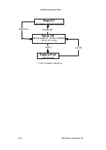
The ink system supplies the printhead with ink at the correct pressure
and viscosity. When the jet is stopped, the system also flushes out the
print head with make--up to provide a clean stop and, when the jet is
next switched on, a clean start.
The printer contains a reservoir of printing ink. As ink is used for
printing, it is replaced by fresh ink from a disposable cartridge. The ink
has a solvent base which (like all solvents) is subject to evaporation, and
this, in turn, affects ink viscosity. The electronic system, therefore,
checks the viscosity regularly and keeps it within carefully controlled
limits by adding make--up, supplied from a second reservoir, which is
also supplied by a disposable cartridge.
Ink Circuit
The ink circuit is shown schematically in the following diagram (see pg.
6--17).
Ink supply
. The printing ink is held in a replaceable reservoir, on
which is mounted a manifold carrying a replaceable cartridge.
Make--up is also held in a reservoir (non--replaceable) and has a
disposable make--up cartridge mounted on it.
The ink cartridge is sealed onto the manifold except for two dip tubes
of different lengths extending down from the manifold into the
reservoir. As the ink level falls below the end of the shorter tube, air is
allowed into the cartridge. Fresh ink is then able to drain through the
longer tube into the reservoir until the ink level rises above the end of
the shorter tube. The ink and make--up levels are monitored by level
sensors in each reservoir. If the ink cartridge is not replaced before the
ink falls below a second level, the printer switches off. However, if the
make--up reservoir is empty the machine can still be used, but the
start--stop performance will be impaired. If make--up is not replaced it
will cause the ink viscosity to increase, and print quality to deteriorate.
The printer also indicates when the ink or make--up levels are too high.
Содержание A-SERIES
Страница 1: ...DOMINO A SERIES INK JET PRINTER OPERATION AND MAINTENANCE MANUAL ...
Страница 6: ... 6 27080 Issue 1 Sept 98 ...
Страница 8: ... 8 27080 Issue 1 Sept 98 ...
Страница 10: ... 10 27080 Issue 1 Sept 98 ...
Страница 12: ...HEALTH AND SAFETY 1 2 27080 Issue 1 August 98 ...
Страница 18: ...HEALTH AND SAFETY 1 8 27080 Issue 1 August 98 ...
Страница 20: ......
Страница 21: ......
Страница 22: ......
Страница 36: ...OPERATION 3 2 27080 Issue 1 August 98 ...
Страница 55: ...DISPLAY MESSAGES AND FAULT FINDING 4 2 27080 Issue 1 August 98 ...
Страница 76: ...REFERENCE 5 4 27080 Issue 1 August 98 ...
Страница 136: ...PRINTER DESCRIPTION 6 20 27080 Issue 1 September 98 ...
Страница 137: ...DESCRIPTION 27080 Issue 1 August 98 6 21 Wiring Diagram 37700W Iss 1 PELTI ER ...
Страница 138: ...DESCRIPTION 6 22 27080 Issue 1 August 98 ...
Страница 140: ...MAINTENANCE 7 2 27080 Issue 1 Sept 98 ...
Страница 142: ...MAINTENANCE 7 4 27080 Issue 1 Sept 98 ...
Страница 156: ...MAINTENANCE 7 18 27080 Issue 1 Sept 98 ...
Страница 158: ...REPAIR 8 2 27080 Issue 1 Sept 98 ...
Страница 192: ...REPAIR 8 36 27080 Issue 1 Sept 98 ...
Страница 198: ...SPARES AND ACCESSORIES 9 6 27080 Issue 1 Sept 98 5 6 7 8 2 3 1 4 9 Print Head General Detail CA002 1 4 4 ...
Страница 200: ...SPARES AND ACCESSORIES 9 8 27080 Issue 1 Sept 98 Ink System General 2 3 5 6 7 8 9 10 11 12 1 MG045_1 4 ...
Страница 202: ...SPARES AND ACCESSORIES 9 10 27080 Issue 1 Sept 98 Ink Management Block 1 2 3 4 5 6 7 8 9 10 6 MG046_1 ...
Страница 204: ...SPARES AND ACCESSORIES 9 12 27080 Issue 1 Sept 98 Electronics Door Assembly A300 A200 1 2 3 4 5 6 7 8 9 MG060_2 ...
Страница 206: ...SPARES AND ACCESSORIES 9 14 27080 Issue 1 Sept 98 Electronics Door Assembly A100 1 2 3 4 5 6 7 A1003_2 ...
Страница 208: ...SPARES AND ACCESSORIES 9 16 27080 Issue 1 Sept 98 Electronics Inner Door 1 2 3 4 5 6 7 ...
Страница 210: ...SPARES AND ACCESSORIES 9 18 27080 Issue 1 Sept 98 Electronics Cabinet MG067_2 1 2 3 4 5 6 7 8 10 11 12 13 14 15 9 ...
Страница 212: ...SPARES AND ACCESSORIES 9 20 27080 Issue 1 Sept 98 ...
Страница 214: ...OPTIONS 10 2 27080 Issue 1 Sept 98 ...
Страница 240: ...OPTIONS 10 28 27080 Issue 1 Sept 98 ...
Страница 242: ...APPENDIX A INSTALLATION A 2 27080 Issue 1 Sept 98 ...
Страница 261: ...APPENDIX B COMPRESSOR DRIVEN AIRDRYER B 2 20950 Issue 1 April 98 ...
Страница 300: ...APPENDIX B COMPRESSOR DRIVEN AIRDRYER 20950 Issue 1 April 98 B 41 37710W Issue 1 Airdryer Wiring Diagram ...
Страница 301: ...APPENDIX B COMPRESSOR DRIVEN AIRDRYER B 42 20950 Issue 1 April 98 AD032_1 Airdryer Power Diagram ...
Страница 302: ...APPENDIX B COMPRESSOR DRIVEN AIRDRYER 20950 Issue 1 April 98 B 43 This page is intentionally blank ...
Страница 310: ...20951 Issue 1 Apr 98 B 1 APPENDIX B AIR DRIVEN AIRDRYER AMENDMENT RECORD Amendment Date All pages at Issue 1 Apr 98 ...
Страница 311: ...APPENDIX B A SERIES AIR DRIVEN AIRDRYER B 2 20951 Issue 1 Apr 98 ...
Страница 313: ...APPENDIX B A SERIES AIR DRIVEN AIRDRYER B 4 20951 Issue 1 Apr 98 ...
Страница 330: ...APPENDIX B A SERIES AIR DRIVEN AIRDRYER 20951 Issue 1 Apr 98 B 21 37709W Issue 1 Airdryer Wiring Diagram ...
Страница 331: ...APPENDIX B A SERIES AIR DRIVEN AIRDRYER B 22 20951 Issue 1 Apr 98 Airdryer Power Diagram AD033_1 ...
Страница 332: ...APPENDIX B A SERIES AIR DRIVEN AIRDRYER 20951 Issue 1 Apr 98 B 23 This page is intentionally blank ...


