PRINTER DESCRIPTION
27080 Issue 1 September 98
6--5
Gutter.
Ink caught in the gutter is drawn back into the ink system for
re--use by a pump in the cabinet. The gutter system in the head consists
of the gutter pipe, a short length of tube, and a gutter sensor consisting
of a length of pipe electrically isolated from the chassis. Ink is detected
by monitoring the electrical continuity through the ink between the
gutter and the gutter sensor.
Ink Pressure.
While the best print quality is given by an optimum ink
working pressure (usually about 2900mbar/42psi or 4000mbar/60psi for
Pinpoint), print quality remains acceptable within certain limits above
or below this pressure. The pressure range between the limits of
acceptable print quality is called the pressure window and depends
upon the type of ink.
Auto--flush.
It is not possible to fully control the drops when the jet is
being started and stopped. To prevent problems caused by scattering
ink drops, a supply of make--up is connected into the drop generator.
When the jet is switched off, the supply to the drop generator is
switched over from ink to make--up. The generator fills with make--up
and the jet becomes make--up, which cleans the nozzle and the gutter.
Any stray drops not collected in the gutter evaporate with very little
residue. At start--up, the make--up in the gunbody is replaced with ink
ready for the head solenoid to open.
Positive Air Supply.
Contaminants can be picked up by the ink drops
in flight, or be drawn with the air into the gutter. Available as options,
a small pump in the printer cabinet or an external air dryer (A300/A200
only)can supply clean air to the print head, maintaining a positive air
pressure inside the head to keep out dust, etc.
CABINET
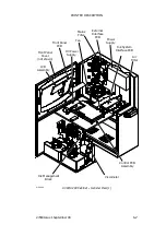
The cabinet is made of stainless steel with doors to two separate
compartments. The upper door carries the printer control panel and is
lockable. The conduit serving the print head and all external
connections enter the left hand side. There are transport handles on
both sides of the cabinet. For stability, the cabinet must be mounted on
a stabiliser kit or stand (see Part 10 : Options). Alternatively, the cabinet
must be bolted to a stable surface.
The upper compartment has a hinged cover plate behind the outer door
that provides both general protection and a mounting surface (on its
inner face) for part of the electronic components.
Содержание A-SERIES
Страница 1: ...DOMINO A SERIES INK JET PRINTER OPERATION AND MAINTENANCE MANUAL ...
Страница 6: ... 6 27080 Issue 1 Sept 98 ...
Страница 8: ... 8 27080 Issue 1 Sept 98 ...
Страница 10: ... 10 27080 Issue 1 Sept 98 ...
Страница 12: ...HEALTH AND SAFETY 1 2 27080 Issue 1 August 98 ...
Страница 18: ...HEALTH AND SAFETY 1 8 27080 Issue 1 August 98 ...
Страница 20: ......
Страница 21: ......
Страница 22: ......
Страница 36: ...OPERATION 3 2 27080 Issue 1 August 98 ...
Страница 55: ...DISPLAY MESSAGES AND FAULT FINDING 4 2 27080 Issue 1 August 98 ...
Страница 76: ...REFERENCE 5 4 27080 Issue 1 August 98 ...
Страница 136: ...PRINTER DESCRIPTION 6 20 27080 Issue 1 September 98 ...
Страница 137: ...DESCRIPTION 27080 Issue 1 August 98 6 21 Wiring Diagram 37700W Iss 1 PELTI ER ...
Страница 138: ...DESCRIPTION 6 22 27080 Issue 1 August 98 ...
Страница 140: ...MAINTENANCE 7 2 27080 Issue 1 Sept 98 ...
Страница 142: ...MAINTENANCE 7 4 27080 Issue 1 Sept 98 ...
Страница 156: ...MAINTENANCE 7 18 27080 Issue 1 Sept 98 ...
Страница 158: ...REPAIR 8 2 27080 Issue 1 Sept 98 ...
Страница 192: ...REPAIR 8 36 27080 Issue 1 Sept 98 ...
Страница 198: ...SPARES AND ACCESSORIES 9 6 27080 Issue 1 Sept 98 5 6 7 8 2 3 1 4 9 Print Head General Detail CA002 1 4 4 ...
Страница 200: ...SPARES AND ACCESSORIES 9 8 27080 Issue 1 Sept 98 Ink System General 2 3 5 6 7 8 9 10 11 12 1 MG045_1 4 ...
Страница 202: ...SPARES AND ACCESSORIES 9 10 27080 Issue 1 Sept 98 Ink Management Block 1 2 3 4 5 6 7 8 9 10 6 MG046_1 ...
Страница 204: ...SPARES AND ACCESSORIES 9 12 27080 Issue 1 Sept 98 Electronics Door Assembly A300 A200 1 2 3 4 5 6 7 8 9 MG060_2 ...
Страница 206: ...SPARES AND ACCESSORIES 9 14 27080 Issue 1 Sept 98 Electronics Door Assembly A100 1 2 3 4 5 6 7 A1003_2 ...
Страница 208: ...SPARES AND ACCESSORIES 9 16 27080 Issue 1 Sept 98 Electronics Inner Door 1 2 3 4 5 6 7 ...
Страница 210: ...SPARES AND ACCESSORIES 9 18 27080 Issue 1 Sept 98 Electronics Cabinet MG067_2 1 2 3 4 5 6 7 8 10 11 12 13 14 15 9 ...
Страница 212: ...SPARES AND ACCESSORIES 9 20 27080 Issue 1 Sept 98 ...
Страница 214: ...OPTIONS 10 2 27080 Issue 1 Sept 98 ...
Страница 240: ...OPTIONS 10 28 27080 Issue 1 Sept 98 ...
Страница 242: ...APPENDIX A INSTALLATION A 2 27080 Issue 1 Sept 98 ...
Страница 261: ...APPENDIX B COMPRESSOR DRIVEN AIRDRYER B 2 20950 Issue 1 April 98 ...
Страница 300: ...APPENDIX B COMPRESSOR DRIVEN AIRDRYER 20950 Issue 1 April 98 B 41 37710W Issue 1 Airdryer Wiring Diagram ...
Страница 301: ...APPENDIX B COMPRESSOR DRIVEN AIRDRYER B 42 20950 Issue 1 April 98 AD032_1 Airdryer Power Diagram ...
Страница 302: ...APPENDIX B COMPRESSOR DRIVEN AIRDRYER 20950 Issue 1 April 98 B 43 This page is intentionally blank ...
Страница 310: ...20951 Issue 1 Apr 98 B 1 APPENDIX B AIR DRIVEN AIRDRYER AMENDMENT RECORD Amendment Date All pages at Issue 1 Apr 98 ...
Страница 311: ...APPENDIX B A SERIES AIR DRIVEN AIRDRYER B 2 20951 Issue 1 Apr 98 ...
Страница 313: ...APPENDIX B A SERIES AIR DRIVEN AIRDRYER B 4 20951 Issue 1 Apr 98 ...
Страница 330: ...APPENDIX B A SERIES AIR DRIVEN AIRDRYER 20951 Issue 1 Apr 98 B 21 37709W Issue 1 Airdryer Wiring Diagram ...
Страница 331: ...APPENDIX B A SERIES AIR DRIVEN AIRDRYER B 22 20951 Issue 1 Apr 98 Airdryer Power Diagram AD033_1 ...
Страница 332: ...APPENDIX B A SERIES AIR DRIVEN AIRDRYER 20951 Issue 1 Apr 98 B 23 This page is intentionally blank ...


