


SuperSigma2 AM PMS
–
V1.5.6 17-1-2020
Page 84 (97)
©2019 DMC GmbH Herten Germany
10
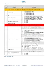
Menu 8
“BDI”
Battery Discharge Indicator
The following menu includes the settings for the BDI algorithm.
Cal.
Ref.
Parameter
Calibrator
text
Min.
adjust
Max.
adjust
Step
size
Default
48V
Default
96V
1
Battery Current Limit Via Can type
BlcCanMsg
0
3
1
0
0
2
Nominal battery voltage
NomBatV
12. 0 V
Uabsmax
1 V
48 V
96 V
3
BDI reset level
BDIreset
12. 0 V
Uabsmax
0.1 V
50.2 V
100.3 V
4
BDI empty level
BDIempty
12. 0 V
Uabsmax
0.1 V
38.9 V
77.8 V
5
BDI warning level
BDIwarn
0 %
99 %
1 %
20 %
20 %
6
BDI cut out level
BDIcut
0 %
99 %
1 %
0 %
0 %
7
BDI speed limit (traction only)
BDIspeed
0.0 Hz
400.0 Hz
0.1 Hz
100.0 Hz
100.0 Hz
8
Drive Battery Current Limit (max. value)
IBattMax
0.0 A
700.0 A
0.1 A
700.0 A
700.0 A
9
Regen Battery Current Limit
IBattReg
0.0 A
700.0 A
0.1 A
700.0 A
700.0 A
M8-1
Battery Current Limit Via Can type “BlcCanMsg”
This setting can be used to enable the dynamic Battery Current Limits (BCL) via Can.
•
If set to
0
Standard Battery with or without static battery current limit according to the setting
Battery Current Limit (max. value) “IBattMax””,
Regen Battery Current Limit “IBattReg””
. BDI (State of
Charge Value) value is calculated inside controller as standard (typical for lead acid battery).
•
If set to
1
Battery with BCL via can enabled. BDI value is calculated inside controller as standard (if standalone
controller set as master or received via DMC can protocol from the master controller if multimotor and set as
slave).
•
If set to
2
Battery with BCL via can enabled. BDI value is received VIA can in the BCL message if controller is
standalone set as master. If slave control receive BDI value from master controller. This option is compatible with
DMC display multimotor application.
•
If set to
3
Battery with BCL via can enabled. BDI value is received VIA can in the BCL regardless is master control
or slave. This option is compatible with multi controller multi battery application (NO DMC display).
If BCL via CAN is enabled controller expect to receive BCL can message.
A timeout timer is enabled in the controller for detecting if BCL can message is coming.
The time out time is fixed to 1s. The suggested refresh rate of BCL message for external BMS or VCU is 400-
500ms.
If a new message is not coming within 1s timeout controller signals F03 S003. It keep pulsing since BCL is not
related to safety. F03 S003 is self-recovery as soon a new BCL message is back.
If BCL is missing the battery current limits set in
Drive Battery Current Limit (max. value) “IBattMax””
and
Regen Battery Current Limit “IBattReg””
are adopted.
In BCL Can message is required VCU/BMS send a toggling security bit. If toggling security bit error occurs F03
S004 is signaled the battery current limits set in
Drive Battery Current Limit (max. value) “IBattMax””
and
Regen Battery Current Limit “IBattReg””
are adopted.
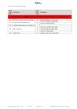
In following table the format of BLC can message is detailed
ID
DLC
Format
unit min max Gain Bytes Start Bit
0XF1x
x = CAN node
number
(BCL Via
CAN)
8
Drive/Delivering Battery Max
current Limit
unsigned int
A
0
7000 1/10 0,1
0
Brake/Regen Battery current
Limit
unsigned int
A
0
7000 1/10 2,3
16
BDI Value / S.O.C.
unsigned int
%
0
1000 1/10 4,5
32
Spare not used
unsigned
char
0
255
1
6
48
Bit 0 Toggle Security Bit
bool
0
1
0
7
56
The unsigned int data assume Motorola data format.
The current limits has a resolution of 0.1 A. The BDI Value/ SOC is in percentage and has a resolution of 0.1%.


