background image

SuperSigma2 AM PMS 

 V1.5.6          17-1-2020 

Page 15 (97) 

©2019 DMC GmbH Herten Germany 

Pin 25


CAN H2 

CAN High communications can line to the Calibrator, Display or other Controller(s) CAN Devices. 


The can communication lines are referred to the battery 0V (ground). 

Pin 26


CAN L2 

CAN Low communications can line to the Calibrator, Display or other Controller(s)/CAN Devices.  


The can communication lines are referred to the battery 0V (ground). 

Pin 27


Sensor 5V / +12V 

Supply  output  for  motor  position/speed  sensor  (Ananlog  Sine/Cosine  or  Hall  Sensor).  It  delivers  5V  or  12V 
according to the parameter 

M4-3 Sensor supply voltage 

“SenSuppV””

 If it is set to 0 the supply is 5V, if set to 1 

supply is 12V. The current capability is 70 mA. 

Pin 28


Hall 1 i/p 

This pin has to be connected to Hall 

sensor channel 1 if Hall sensor technology is selected by means of 

M4-2 

Sensor technology 

“SensType”” (set to 1).


Pin 29


Hall 2 i/p 

This pin has to be connected to Hall sensor channel 2 if Hall sensor technology is selected by means of 

M4-2 

Sensor technology 

“SensType”” (set to 1).


Pin 30


Hall 3 i/p 

This pin has to be connected to Hall sensor channel 3 if Hall sensor technology is selected by means of 

M4-2 

Sensor technology 

“SensType”” (set to 1).


Pin 31


Sensor supply 0V 

This pin is the ground line for speed/position sensor. 

Pin 32


Motor Sensor Sine 

This pin has to be connected to Sine output of analog sine cosine sensor if SineCos sensor technology is selected 
by means of 

M4-2 Sensor technology 

“SensType”” (set to 0).


Pin 33


Motor Sensor CoSine 

This pin has to be connected to Cosine output of analog sine cosine sensor if SineCos sensor technology is selected 
by means of 

M4-2 Sensor technology 

“SensType”” (set to 0).


Pin 34


Thermistor AD4 i/p 

This pin has to be connected to the anode of KTY84-130 thermistor or to one side of and Pt 1000 ohm 0°C thermal 
sensor.  The  motor  thermal  sensor  type  can  be  selected  by  parameter 

M7-1  Motor  Temp  Sensor  Type 

“MtempTyp””


Pin 35


Thermistor 0V 

This pin has to be connected to the cathode (black lined side) of KTY84-130 thermistor or Pt 1000 ohm 0°C thermal 
sensor.  The  motor  thermal  sensor  type  can  be  selected  by  parameter 

M7-1  Motor  Temp  Sensor  Type 

“MtempTyp””


Содержание SuperSigma2

Страница 1: ...ous motors ADVANCED MANUAL V 1 5 6 This user manual details the features of the standard controller range PMS range 24 96V 250 600Arms Preliminary information we reserve the right to update and or modify this manual at any time without prior notice ...

Страница 2: ...j 17 in traction for torque mode 3 for better end of braking in footbrake operation Changed some default values Included Park Icon for display Improved F12 and F13 management Improved PC interface settings download Improved the function inhibit of change of direction 1 4 1 24 08 2018 FM Update Layout and Cross references Minor textual errors corrected 1 4 2 15 01 2019 FM Update Nominal RMS motor c...

Страница 3: ...net Brake Fan control 14 Pin 17 Contactor 3 o p Powersteer Fan control 14 Pin 18 Digital o p Remote LED or Brake lights or Drive OK 14 Pin 19 Supply 12V 70mA max 14 Pin 20 CAN 12V 70mA max 14 Pin 21 CAN H1 14 Pin 22 CAN L1 14 Pin 23 CAN 0V 14 Pin 24 CAN 120R Link 14 Pin 25 CAN H2 15 Pin 26 CAN L2 15 Pin 27 Sensor supply 5V 12V 15 Pin 28 Hall 1 i p 15 Pin 29 Hall 2 i p 15 Pin 30 Hall 3 i p 15 Pin 3...

Страница 4: ... M1 31T Foot Brake Torque 1 Torque Mode Only FBrkTrq1 36 M1 32T Foot brake ramp time 1 FBrkRmp1 36 M1 33T Cutback speed 2 I O 5 6 set to Speed Speed2 37 M1 34T Inching time I O 5 6 set to Inching InchTime 37 M1 35T Acceleration delay 2 Accel2 37 M1 36T Deceleration delay 2 Decel2 37 M1 37T Maximum Drive Torque 2 Torque Mode Only MxDrTrq2 37 M1 38T Neutral Brake Torque 2 Torque Mode Only NBrkTrq2 3...

Страница 5: ...Speed threshold to end braking ZSpdTh 44 4 MENU 2 STATUS 45 4 1 STATUS TABLES 46 M2 3 BDI States table 46 M2 6 Drive and brake status table 46 M2 7 Speed limits table 46 M2 8 Torque limits table 46 M2 9 Motor limits table 46 5 MENU 3 CONTROLLER SETUP 47 5 1 MENU 3 CONTROLLER SETUP FOR TRACTION 47 M3 1T Accel Characteristic Lin Curv 49 M3 2T Control Mode Spd Torq 49 M3 3T Proportional direction bra...

Страница 6: ...Digital Output 2 pull in voltage Do2PlInV 61 M3 15P Digital Output 2 hold voltage Do2HoldV 61 M3 16P Digital Output 3 pull in voltage Do3PlInV 61 M3 17P Digital Output 3 hold voltage Do3HoldV 61 M3 18P Driver output 2 configuration Drv2Cfg 61 M3 19P Driver output 3 configuration Drv3Cfg 62 M3 20P Motor Temperature threshold for output driver MotTmpTh 62 M3 21P Controller Temperature threshold for ...

Страница 7: ...ge Limiter Filter Frequency FVlimFlt 72 8 MENU 6 PMS MOTOR ADVANCED 73 M6 1 Decouple Iq and Id controllers Decouple 73 M6 2 Enable software PWM algorithm delay compensation PWMDelay 73 M6 3 Limit torque controller during Voltage limiting VoltSat 73 M6 4 Speed Control Filter SCFilter 73 M6 5 Enable Voltage Limiter VoltCtrl 73 M6 6 Speed filter cut off frequency Fspdfilt 73 M6 7 Percentage of correc...

Страница 8: ...BDI cut out level BDIcut 85 M8 7 BDI speed limit BDIspeed 85 M8 8 Drive Battery Current Limit max value IBattMax 85 M8 9 Regen Battery Current Limit IBattReg 85 11 MENU 9 CAN BUS SETUP 86 M9 1 CAN Node Number CAN node 87 M9 2 CAN bit rate CANbitRt 87 M9 3 Transmit Receive CAN messages CANMsgs 87 M9 4 Shared Line Contactor ShareLC 87 M9 5 Last Node Sharing Line Contactor LstNode 88 M9 6 Can Control...

Страница 9: ...and time efficient setup of a DMC Supersigma2 Controller The SuperSigma2 has 9 parameter menus which can be set up but several settings are displayed based upon the choice of other settings in different menus For a clear Controller tuning the following procedure should be adopted 1 Enter the Menu 3 Controller Setup and set up the basic controller settings Mind that the setting of several parameter...

Страница 10: ...ter can be used to lift the forks on a forklift truck If the pump potentiometer has a switch the switch has to be connected to this input The programmable parameter M3 5P Enable pot with switch NoSw Sw has to be set to 1 Under these conditions the pump motor will drive if the input is active and the potentiometer is activated Pin 2 Reverse i p Pump Switch 2 Traction Reverse i p Activating this inp...

Страница 11: ... spin at a speed set by the programmable parameter M1 9P Speed 5 demand Pspeed5 Pin 6 Speed Limit 2 Inch Reverse Pump Switch 6 Power Steer Input Traction Speed Limit 2 Inch Reverse The function of this input is defined by the programmable parameter M3 5T I O Pin 5 and 6 Sp In Ad If set to Spd 0 then this input can be used to limit the speed of the vehicle to a value set by the programmable paramet...

Страница 12: ... Traction This is an analogue input that will accept a 3 wire 5kΩ potentiometer or a 0V to 5V voltage signal electronic accelerator The active range of the accelerator input is defined by the programmable parameters M1 52T Accelerator pot minimum AccMin and M1 53T Accelerator pot maximum AccMax Two kinds of accelerator can be selected by means of parameter M3 12T Accelerator type AccelTyp If Accel...

Страница 13: ...nly in traction applications The function is activated by means of parameter M3 14T Single or Dual Motor Si DL DR in the Controller Set up menu It is activated both if set to 1 Dual Motor Left or 2 Dual Motor Right or 3 Single Motor with steer pot Speed limit Right The input can be connected to a 3 wire 5kΩ potentiometer that measures the steering angle of the vehicle The active range of the input...

Страница 14: ...o drive a cooling fan when motor and or controller temperature sensors signal that the temperature is above a specified threshold Pin 18 Digital o p Remote LED or Brake lights or Drive OK The function of this output is set in Menu 3 Controller Setup for both traction and pump applications Depending on the application considered it can be used or as a remote LED or as a Dirve OK signal or for tract...

Страница 15: ...is selected by means of M4 2 Sensor technology SensType set to 1 Pin 30 Hall 3 i p This pin has to be connected to Hall sensor channel 3 if Hall sensor technology is selected by means of M4 2 Sensor technology SensType set to 1 Pin 31 Sensor supply 0V This pin is the ground line for speed position sensor Pin 32 Motor Sensor Sine This pin has to be connected to Sine output of analog sine cosine sen...

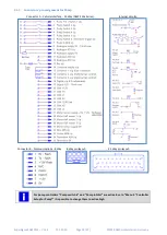
Страница 16: ...g of PMS controller 2 1 1 Connectors pin assignment for Traction Connector A Vehicle Interface 35 Way AMP SEAL Series Internal circuits Connector B Communications 8 Way 8 Way pin layout 35 Way pin layout Most inputs are Normally Open NO except for the speed inputs these are Normally Closed NC ...

Страница 17: ...SuperSigma2 AM PMS V1 5 6 17 1 2020 Page 17 97 2019 DMC GmbH Herten Germany 2 1 2 Light wiring example for traction The reported wiring example is referred to active low inputs ...

Страница 18: ...gnment for Pump Connector A Vehicle Interface 35 Way AMP SEAL Series Internal circuits Connector B Communications 8 Way 8 Way pin layout 35 Way pin layout For pump controllers Pump switch 6 and Pump inhibit are active low In Menu 3 Controller Setup for Pump it is possible to change them to active high ...

Страница 19: ...SuperSigma2 AM PMS V1 5 6 17 1 2020 Page 19 97 2019 DMC GmbH Herten Germany 2 1 4 Light wiring example for pump The reported wiring example is referred to active low inputs ...

Страница 20: ... is activated a lamp can be connected between the digital input and the B or Vbatt terminal lamp is optional 2 2 1 2 Using an electronic switch An active low digital input can be activated using an electronic switch The electronic switch is powered with a supply voltage greater than 3V3 The digital output of this electronic switch is high when not activated which results in an output voltage great...

Страница 21: ...the digital input and the B or GND terminal lamp is optional 2 2 2 2 Using an electronic switch supplied with more than 12V An active high digital input can be activated using an electronic switch When the electronic switch is powered with a supply voltage greater than 12V for example Vbatt the digital output can be directly wired to one of the digital inputs 2 2 2 3 Using an electronic switch sup...

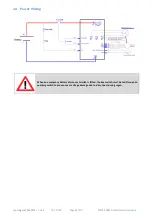
Страница 22: ...2020 Page 22 97 2019 DMC GmbH Herten Germany 2 4 Power Wiring When an emergency battery disconnect switch is fitted the key switch must be fed through an auxiliary switch to prevent over voltage damage due to disconnect during regen ...

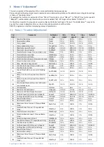
Страница 23: ...change speed MxDbrkSp 1 100 1 100 13 Foot brake torque torque mode only FBrake 0 100 1 50 14 Foot brake ramp time FbrkRamp 0 1 s 20 0 s 0 1 s 1 0 s 15 Speed threshold to enter end of braking mode SpdThEbM 0 1 50 0 0 1 15 16 Ramp time from the speed threshold to zero SpdRmpTm 0 1 s 20 0 s 0 1 s 3 0 s 17 Ramp time from the speed threshold to zero low TH SpdRTmFB 0 1 s 20 0 s 0 1 s 0 4 s 18 Zero Spee...

Страница 24: ... V 10 0 V 0 1 V 2 0 V 61 Dual motor cut out DMcut 1 100 1 10 62 Dual motor angle 1 DMang1 1 100 1 60 63 Dual motor angle 2 DMang2 1 100 1 70 64 Dual motor angle 3 DMang3 1 100 1 85 65 Dual motor speed 1 DMspd1 0 100 1 10 66 Dual motor speed 2 DMspd2 0 100 1 5 67 Dual motor speed 3 DMspd3 0 100 1 30 68 Speed ratio display Kph SpdRatio 1 0 999 9 0 1 120 0 69 Vehicle max speed VmaxSpd 0 0 KPH 999 9 K...

Страница 25: ...mum speed reverse SpdMaxR This limits the maximum reverse speed of the motor Maximum Reverse Speed should not be set to a value higher than the parameter M4 13 Maximum Motor Frequency Fmotmax If SpdMaxR is set higher the maximum forward speed of the vehicle will be the M4 13 Maximum Motor Frequency Fmotmax M1 7T Neutral Brake torque NBrake This parameter is active only in torque mode This sets the...

Страница 26: ... is stopped according to neutral brake settings M1 8T Neutral brake ramp time NBrkRamp M1 7T Neutral Brake torque NBrake and the controller signals a fault III If the motor speed is above MdDbrSp and neutral is selected the motor slows down according to neutral brake settings M1 8T Neutral brake ramp time NBrkRamp M1 7T Neutral Brake torque NBrake When the speed drops below MxDbrSp it is possible ...

Страница 27: ...100 the Accelerator must be tuned properly In fact the drive direction change is allowed when speed is below the threshold and if accelerator is fully released its value is 0 To avoid strange behavior check if with accelerator fully released the signal is 0 by reading the line 9 and 10 of Test menu by means of calibrator If not the Adjustment 51 AccMin has to be increased For example if with accel...

Страница 28: ...released In case the footbrake is pressed the ramp time to zero speed will be derived based on the brake pot value between this parameter and M1 17T Foot Brake Speed threshold Ramp time to zero speed SpdRTmFB M1 17T Foot Brake Speed threshold Ramp time to zero speed SpdRTmFB This parameter is only active when M3 2T Control Mode Spd Torq is set to 3 It defines the ramp time to reach zero speed when...

Страница 29: ...ral brake ramp time NBrkRamp if neutral braking is happening or M1 14T Foot brake ramp time FbrkRamp if foot brake is operated 2 when speed is below setting M1 15T Speed threshold to enter end of braking mode SpdThEbM the controller reduces speed in a smooth way according to M1 16T Speed threshold Ramp time to zero speed SpdRmpTm 3 when speed is below M1 18T Zero Speed Threshold to enter hill hold...

Страница 30: ...or to M1 13T Foot brake torque FBrake and the Brake pot value refer to M1 54T Brake pot minimum BrkMin and M1 55T Brake pot maximum BrkMax if foot brake is operated 2 when speed is below setting M1 15T Speed threshold to enter end of braking mode SpdThEbM the controller reduces brake torque in a smooth way proportionally to speed to assure a smooth stop operation 3 when speed is below M1 18T Zero ...

Страница 31: ...rque FBrake and the Brake pot value refer to M1 54T Brake pot minimum BrkMin and M1 55T Brake pot maximum BrkMax if foot brake is operated 2 when speed is below setting M1 15T Speed threshold to enter end of braking mode SpdThEbM the controller reduces brake torque in a smooth way proportionally to speed to assure a smooth stop operation 3 when speed is below M1 18T Zero Speed Threshold to enter h...

Страница 32: ...3T Foot brake torque FBrake and the Brake pot value refer to M1 54T Brake pot minimum BrkMin and M1 55T Brake pot maximum BrkMax 2 when speed is below setting M1 15T Speed threshold to enter end of braking mode SpdThEbM the controller starts to control speed The ramp time to zero is derived according to the brake pot position between M1 16T Speed threshold Ramp time to zero speed SpdRmpTm and M1 1...

Страница 33: ...peed SpdRmpTm 3 when speed is below M1 18T Zero Speed Threshold to enter hill hold or neutral brake end ZSpdTh the vehicle is held still until M1 19THill hold time HHTime time is elapsed The vehicle is kept still by means of speed control algorithm 4 when M1 19THill hold time HHTime is elapsed two situations are possible I if the vehicle is on a slope it will roll back or forward according to the ...

Страница 34: ...low M1 18T Zero Speed Threshold to enter hill hold or neutral brake end ZSpdTh the controller starts to control speed slowing linearly down to zero according to M1 16TSpeed threshold Ramp time to zero speed SpdRmpTm 4 when the vehicle stops it enters in Hill Hold mode and is held still until M1 19THill hold time HHTime time is elapsed The vehicle is kept still by means of speed control algorithm 5...

Страница 35: ...is below setting M1 15T Speed threshold to enter end of braking mode SpdThEbM the controller starts to control speed The ramp time to zero is derived according to the brake pot position between M1 16T Speed threshold Ramp time to zero speed SpdRmpTm and M1 17T Foot Brake Speed threshold Ramp time to zero speed SpdRTmFB 3 when speed is below M1 18T Zero Speed Threshold to enter hill hold or neutral...

Страница 36: ... Inching speed I O 5 6 set to Inching InchSpd The function of this parameter is dependent on the setting of M3 5TI O Pin 5 and 6 Sp In Ad in the Controller Set up menu which sets whether pins 5 and 6 are used as speed limiting inputs or inching control inputs or advanced mode If set to 0 Speed Limits this set is not active If set to 1 Inching then Inching Speed sets the speed of the vehicle in bot...

Страница 37: ... mode is selected from controller setup M3 5TI O Pin 5 and 6 Sp In Ad They define the corresponding ramp times and torque levels for the different situations driving and neutral foot direction braking when the switches connected to inputs 5 and 6 are configured to select Drive Style 2 refer to Control set up M3 5TI O Pin 5 and 6 Sp In Ad for configuration details M1 44T Cutback speed 3 I O 7 set t...

Страница 38: ...put normal or wig wag can be configured via the parameter M3 12T Accelerator type AccelTyp When the accelerator is properly set it reaches 100 when full pressed and sets the motor speed or torque demand according to parameter M3 2TControl Mode Spd Torq In Speed Mode when accelerator reaches 100 the motor speed demand correspond to 100 of actual speed limiting If for example M1 22T Cutback speed 1 ...

Страница 39: ...gle or Dual Motor Si DL DR in the Controller Set up menu is set different from 0 When active dual motor left dual motor right single motor with steer pot speed limitation this parameter sets the voltage on the Steering Pot input Pin 12 Analogue AD3 Steer pot which will correspond to the maximum steering angle By convention the maximum steering angle relates to the full right hand lock of the vehic...

Страница 40: ...angle is between M1 62T Dual motor angle 1 DMang1 and M1 63T Dual motor angle 2 DMang2 the torque of the inner motor is zero meaning it is able to freewheel and the speed is left free When the steering angle is beyond M1 63T Dual motor angle 2 DMang2 and towards M1 64T Dual motor angle 3 DMang3 the inner motor reverses its spinning direction and torque is increased towards half the demanded torque...

Страница 41: ...d3 60 If the steering pot is between 10 the speed limit is kept to 100 and it corresponds to a central dead band If the steering pot is between 10 and 85 left or right the speed limit is reduced gradually to 60 If steering pot is greater than 85 speed limit is kept to 60 The speed limit is expressed as percentage of parameter M4 13 Maximum Motor Frequency In fact if for example M4 13 Maximum Motor...

Страница 42: ...safe stop function is enabled ref to M9 6 Can Control Type CANCtTyp For details refer to application note 1 SuperSigma2 AN 160105 SuperSigma2 Can HMI Protocol V1 7 M1 72T Belly switch speed BellySpd M1 73T Belly switch time BellyTim These two settings are active if Walkie type vehicle is enabled M3 8T Vehicle type select Ride Wlk set higher than 0 In a vehicle of this kind if input Pin 3 Footswitc...

Страница 43: ...l speed that the pump will adopt on entering drive Increasing the value will help minimize any delay from selecting drive to creeping the pump The value relates to the motor speed i e the motor s rotor frequency M1 4P Creep speed Ramp CreepRmp This parameter sets the ramp time for applying creep speed M1 5P Maximum pot speed 1 Potmax1 This sets the pump speed when the switch wired to pin 1 of 35 w...

Страница 44: ...to the speed demand from input 6 using the rates defined by parameter M1 12P Acceleration delay for speed 6 demand pwrStr Paccel6 M1 11P Minimum motor speed in cutback conditions MinSpeed If some performance limitation is active Low voltage I2T Performance Table Motor Overtemperature Controller Overtemperature Undervoltage and it is limiting the speed below this value the motor is stopped and a fa...

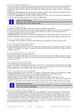
Страница 45: ...im See M2 7 Speed limits table 8 Torque Limit TrqLimit See M2 8 Torque limits table 9 Motor Limit MotorLim See M2 9 Motor limits table 10 Battery Voltage BatVolts 0 1 V Max Voltage 11 Capacitor Voltage CapVolts 0 1 V Max Voltage 12 Battery current I_batter 0 1 A 13 Motor current I_Motor 0 1 Arms Id Current Iq Current 14 Motor voltage V_Motor 0 1 Vrms Reactive Power Motor Power Reached maximum outp...

Страница 46: ...S1 Speed 1 limit S2 Speed 2 limit S3 Speed 3 limit S4 Speed 4 limit S5 Speed 5 limit S6 Speed 6 limit SI Inching SB BDI speed limit SH Hand brake speed limit SV Control Via CAN HMI limit CS Controller over temperature limit SS Steering Pot Speed Limit M2 8 Torque limits table Limit Description CT Controller temperature MT Motor temperature PT Performance table current limit TC Timed Current Limit ...

Страница 47: ...igger PsF FR S 0 FS1 1 Fwd Rev 2 Seat switch 3 FS1 and rotor speed 4 FS1 Fwd Rev FootBrake in AN or DIG 0 4 8 Vehicle type select Ride Wlk 0 Ride on 1 Walkie 2 Walkie allows to drive slowly speed 3 speed with tiller switch open and only when speed 3 is active 0 2 9 Tiller Function TillFunc 0 Normal response 1 fast response 2 immediate response 0 2 10 Belly switch disabled at zero speed BellFunc 0 ...

Страница 48: ... to 100 C Default is 45 C 10 100 C 23 Line Contactor pull in level LCPlInLv Adjustable from 50 to 100 Ubatt to limit inrush current Default is 90 50 100 24 Line Contactor pull in time out LCPlInTO Line Contactor pull in time out Default is 10sec 0 12 sec 25 Drive torque during braking DTrq Brk 0 no drive torque allowed during brake 1 drive torque is allowed during brake 0 1 26 Line Contactor Coil ...

Страница 49: ...ch type is detailed below Speed control means that the Accelerator input is used as a speed demand between zero and the programmed maximum speed for the direction of drive Speed control results in a constant drive speed for a given demand Accelerator deflection regardless of load Torque control means that the Accelerator input is used to set a torque demand between zero and the programmed maximum ...

Страница 50: ...ith speed mode for the end of braking If set to 0 Coast then there is no restraint function and the vehicle is free to coast when zero speed is reached and M1 9T Neutral brake End delay NBrkEnd time is elapsed If set to 1 Hill Hold Restraint the controller at the end of braking will manage the vehicle with hill hold function Following neutral braking by opening Foot switch in Ride On vehicle or se...

Страница 51: ...ach drive style it is possible to set up different ramp times for torque and speed and different driving and braking torque level Inputs 5 and 6 will operate as normally closed switches input For the three different drive styles the following set of parameters are adopted i Normal Drive Style input 5 closed input 6 closed M1 1T Acceleration delay Accel M1 2T Deceleration delay Decel M1 7T Neutral ...

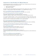
Страница 52: ...e power steering to remain active The length of the delay is set by the parameter M1 50T Power steer delay PStrDly If set to 0 Footswitch then the power steer contactor is driven at the instant the Footswitch pin 3 of 35 Way Connector is closed If set to 1 Forward Reverse then the power steer contactor is driven at the instant either the Forward Switch pin 1 of 35 Way Connector or the Reverse Swit...
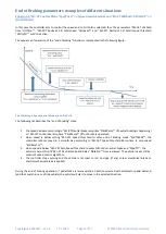
Страница 53: ...e M3 11T Display Status field Of D V K This sets the type of information that will appear in the General Indication Field of the Sigmagauge or the DMC Display If set to 0 None then the General Indication Field will be blank If set to 1 Accelerator Demand then the Accelerator Demand as a percentage will be displayed from 0 to 100 If set to 2 Motor Velocity then the motor velocity speed in units of ...

Страница 54: ... and M1 61T Dual motor cut out DMcut are therefore active and used to set up the speed limit as a function of steering potentiometer When a Dual Motor selection is made the speed and torque when steering will change as described by the parameters from M1 61T Dual motor cut out DMcut to M1 67T Dual motor speed 3 DMspd3 This parameter requires a key cycle off on to be effective IMPORTANT Dual motor ...
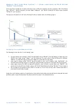
Страница 55: ...otor Temperature threshold for output driver MotTmpTh OR if controller temperature is higher than threshold M3 22T Controller Temperature threshold for output driver CtrTmpTh while it is deactivated when motor temperature gets lower than threshold M3 21T Motor Temperature threshold for output driver MotTmpTh 8 C of hysteresis AND controller temperature gets lower than threshold M3 22T Controller T...

Страница 56: ... 75 If it set to 100 the full battery voltage will be applied for 1 s M3 27T Line Contactor Coil holding voltage LCHoldVl It sets the line contactor coil holding voltage applied when the line contactor is closed and 1 s of time is elapsed It is expressed as percentage of the M8 2 Nominal battery voltage NomBatV in the BDI menu Example M8 2 Nominal battery voltage NomBatV is set to 48V and the desi...

Страница 57: ...3T Calibration Data option CalValue Not used yet For future development M3 34T Loading Default LoadDefs If this parameter is set to 1 load defaults all the setting in all menus will be restored to the default factory values This parameter requires a key cycle off on to be effective ...

Страница 58: ...ff detection enabled 3 Both 0V and 5V wire off detection 0 3 10 Line Contactor pull in level LCPlInLv Adjustable from 50 to 100 Ubatt to limit inrush current Default is 90 50 100 11 Line Contactor pull in time out LCPlInTO Line Contactor pull in time out Default is 10sec 0 12 sec 12 Line Contactor Coil pull in Voltage LCPlInVl Adjustable from 5 to 100 Ubatt Default is 100 7 100 13 Line Contactor C...

Страница 59: ...to 1 NC the input will be active when a switch connected to pin 7 is open If inhibit input Pin 7 Speed Limit 3 Handbrake Pump Inhibit becomes active it immediately stops the pump and signals failure F 03 Inhibit input is not active on input 6 Power steer thus if input 6 is active and inhibit is activated the pump is still work signaling failure F 03 M3 4P Enable power up checks Nchk Chk This sets ...

Страница 60: ...the input is tied to battery ground and inactive when not connected An internal pull up resistor will be enabled If set to 1 Digital inputs Active high the digital inputs will be considered active when the input is tied to battery plus and inactive when not connected An internal pull down resistor will be enabled For the Digital Inputs connection and wiring details refer to section 2 2 Selecting a...

Страница 61: ...tal Output 3 hold voltage Do3HoldV It sets the Digital Output 3 holding voltage applied when the line contactor is closed and 1 s of time is elapsed It is expressed as percentage of the M8 2 Nominal battery voltage NomBatV in the BDI menu If it set to 100 the full battery voltage will be applied M3 18P Driver output 2 configuration Drv2Cfg This sets the configuration for Driver Output 2 If set to ...

Страница 62: ...threshold M3 21T Motor Temperature threshold for output driver MotTmpTh OR if controller temperature is higher than threshold M3 22T Controller Temperature threshold for output driver CtrTmpTh while it is deactivated when motor temperature gets lower than threshold M3 21T Motor Temperature threshold for output driver MotTmpTh 8 C of hysteresis AND controller temperature gets lower than threshold M...

Страница 63: ... are printed on the motor name plate or provided on a datasheet This basic set consists of the following parameters Auto Tuning Parameter Brief description Number of motor poles Set the number of poles Sensor technology Choose analogue Sin Cos sensor or Hall sensors Sensor encoder supply voltage Choose 5 volt or 12 volt sensor supply Reverse sensor reading Try set to 1 if auto tuning diagnostics r...

Страница 64: ... 0 16 Sin Cos Sensor Delay Angle at 100 Hz SensDel 0 0 deg 15 0 deg 0 1 deg 3 6 deg 17 Auto Tuning Type 0 Standard auto tuning position sensor tuning 1 Full autotuning position sensor Inductance and Ke mesurment ATuneType 0 1 1 0 If a parameter with one star is changed recalculation is required Recalculation is performed after setting the recalculation parameter to 1 and recycling the key 7 The no...

Страница 65: ...ning procedure is performed If a change is required it is necessary to cycle the key and repeat the auto tuning procedure M4 8 RMS motor current For tuning Ifor AT This parameter sets the motor nominal current for autotuning It has to be set equal to 30 40 of motor continuous current It is read by the controller only after key cycle power off on and will have effect only after the first auto tunin...

Страница 66: ...is parameter to 1 and key power off on cycled The internal motor parameters will be optimized considering the changes in the motor or autotuning menus M4 16 Sin Cos Sensor Delay Angle at 100 Hz SensDel This setting corresponds to the angle delay at 100 Hz of the sine cosine position sensor As default is set to 3 6 degrees Refer to sensor manufacturer documentation for this information This value i...

Страница 67: ...action controllers For Pump controllers Again confirm by pressing and holding the and button for at least 5 seconds When Auto Tuning has started the following screen is shown Auto tuning can be stopped at any time by pressing any calibrator button After the auto tuning process is finished the following screen will be shown In case of errors the following screen will be shown In case of an error ve...

Страница 68: ...ion 7 Wrong number of poles set in M4 1 Number of motor poles only for Sin Cos 8 Unable to finish calculation rotor resistance too low or too high 9 Unable to finish motor measurements Probably causes 1 Motor is loaded remove mechanical load 2 Nominal current it is set to low increase M4 8RMS motor current For tuning 3 Motor inductance is too low 10 Sine Cosine signal is not detected check wiring ...

Страница 69: ... the full torque is not strong enough do the actions indicated in the following list 1 Be sure that autotuning procedure has been executed and ended properly with no failure code 2 If M4 9 Maximum RMS motor current is lower than controller maximum current increase it and execute recalculation procedure see paragraph 6 5 Recalculation This operation is possible in case the motor can manage an highe...

Страница 70: ... 5 100 1 60 16 Torque Reduction Map in field weakening range point 5 TReduc5 5 100 1 50 17 Capacitor Voltage ramp Time CapVTime 0 1 s 20 0 S 0 1 S 0 1 S 18 Voltage Limiter Filter Frequency FVlimFlt 0 1 Hz 100 0 Hz 0 1 Hz 100 0 Hz M5 1 Proportional gain speed controller Kp Spd In torque mode it determines how aggressively the speed controller limits the speed of the motor to the active speed limit ...

Страница 71: ...er Ki Spd This is applied if M5 3 Enable double PI settings for speed controller SpdPIx2 is set to 1 and actual speed is above M5 4 Double PI speed threshold SpdPITH M5 7 Transition time between the two PI settings for the speed controller TransTim This parameter sets the time is needed for moving from low speed gains to high speed gains and vice versa A too small value can produce a bumpy transit...

Страница 72: ...ond to the motor reduction current map in field weakening Since the PMS motor field weakening capability is limited in order to achieve a wide speed range a torque current limitation map is introduced with the name of motor torque current reduction map It is automatically calculated at the end of autotuning and the settings are available in Motor Setup Menu see figure below It is also adjusted eve...

Страница 73: ...uple M6 2 Enable software PWM algorithm delay compensation PWMDelay M6 3 Limit torque controller during Voltage limiting VoltSat M6 4 Speed Control Filter SCFilter M6 5 Enable Voltage Limiter VoltCtrl M6 6 Speed filter cut off frequency Fspdfilt M6 7 Percentage of correction for inductance value DecoLeak M6 8 Back EMF correction factor BEMFCorr These parameters are only for advanced DMC servicing ...

Страница 74: ...rror threshold LVerror 14 0 V Unit max 0 1 V 14 0 V 48 V units 18 High Voltage Cut Back start threshold HVCBstrt 24 0 V 67 5 V 0 1 V 60 0 V 19 High voltage cut back end threshold HVCBend 24 0 V 67 5 V 0 1 V 67 5 V 20 High voltage error threshold HVerror 24 0 V 70 0 V 0 1 V 70 0 V 96 V units 18 High Voltage Cut Back start threshold HVCBstrt 24 0 V 138 5 V 0 1 V 130 0 V 19 High voltage cut back end ...

Страница 75: ...ronounce as I squared t that is a current limiting feature the maximum current is limited with time A detailed description of the function and how to set its parameters is following Heat dissipation When current is flowing through the motor some electrical losses are present since the motor is not ideal and they result in heating up the motor The heat dissipation is a squared function of the curre...

Страница 76: ...motor temperature will rise to a temperature of 155 C and will stabilize there See also the graph below Cooling Of course cooling will have an influence in the maximum allowable operation temperature It may happen that with sufficient cooling the maximum allowable operation temperature is not reached Or in a worse case the temperature rises beyond the maximum allowable operation temperature In tha...

Страница 77: ...centages These need to be configured in the Menu 7 Limits Setup of the controller A limit will run from 100 no cut back to 0 full cut back This is displayed also in the Status Menu at Drive torque limit When the I2 t feature is actually limiting the current the Status menu will show T1 T2 or T3 limit indication depending in which phase the I2 t function currently is The reason that percentages are...

Страница 78: ...miting the most will apply the limit The Drive torque limit will then show the limit of the corresponding module Example Controller temperature limit 50 I2 t feature 80 Applicable limit 50 Applicable module Controller temperature indicated by CT M7 9 Performance Table Speed 1 PTSpd1 M7 10 Performance Table Speed 2 PTSpd2 M7 11 Performance Table Speed 3 PTSpd3 M7 12 Performance Table Cutback 1 PTCu...

Страница 79: ...s when performance table is being set not in the correct order When finish to set up the performance table recycle the key If F7 S709 is there it means that in the Performance table settings are not consistent Here the situations that gives F7 S709 if Performance Table Cutback 1 is lower than Performance Table Cutback 2 or Performance Table Cutback 2 is lower than Performance Table Cutback 3 it is...

Страница 80: ...rive power it will not be noticed But when the user demands more drive power the drive power is limited to the maximum drive power available When this occurs the Status menu of the controller shows the LV limit indication Also the error F02 is displayed during low voltage cut back The maximum drive power limit will run from 100 no cut back to 0 full cut back This is displayed also in the Status Me...

Страница 81: ...to the maximum brake power available When this occurs the Status menu of the controller shows the HV limit Also the error F04 is displayed during high voltage cut back The maximum brake power limit will run from 100 no cut back to 0 full cut back This is displayed also in the Status Menu at BrakeTqLim High voltage limit The high voltage limit is the absolute limit of the controller and the motor W...

Страница 82: ...When the controller is using speed control or is in a speed limit the user is thinking he is driving the motor but it is possible that the controller is braking the motor in order to control the speed This is also a form of braking and here the high voltage cut back applies as well M7 21 Absolute maximum motor speed AbsMaxSp For safety reason a motor overspeed fault detection is active in software...

Страница 83: ... Low current threshold ImaxLow After the reduction has occurred the maximum current output will remain at the lower level for a period of 3 times the M7 26 Timed Current Limit Timer IthTime If necessary once this period has expired the current can then be returned to its original level Example This sets the period of time which if exceeded will initiate a reduction in the controller s maximum curr...

Страница 84: ...et as master If slave control receive BDI value from master controller This option is compatible with DMC display multimotor application If set to 3 Battery with BCL via can enabled BDI value is received VIA can in the BCL regardless is master control or slave This option is compatible with multi controller multi battery application NO DMC display If BCL via CAN is enabled controller expect to rec...

Страница 85: ...nt effect between traction and pump software and can be disabled by setting it to 0 In traction software this sets the level of battery voltage at which the speed of the vehicle will be limited to a value set by the parameter M8 7 BDI speed limit BDIspeed The value is set as a percentage where 100 corresponds to parameter M8 3 BDI reset level BDIreset and 0 corresponds to parameter M8 4 BDI empty ...

Страница 86: ...mit only Transmit only Transmit only Transmit only Transmit only Transmit only 4 DC drive command DS drive status MS Motor status CS controller status receive transmit transmit transmit 4 Shared Line Contactor ShareLC 0 No shared line contactor 1 Shared line contactor 2 Shared line contactor CAN HMI master 3 Shared line contactor CAN HMI slave 0 5 Last Node Sharing Line Contactor LstNode Node numb...

Страница 87: ...bitrate is 100 kbit s If set to 1 the bitrate is 125 kbit s If set to 2 the bitrate is 250 kbit s The change is active only after a key power off on cycle VERY IMPORTANT if the bit rate of the controller is changed also the calibrator bit rate has to be changed to communicated again with the controller To change the calibrator bit rate follow this procedure 1 Press and hold the SEL button for more...

Страница 88: ...s CANMsgs set to 4 and therefore M9 4 Shared Line Contactor ShareLC is set to 0 or 1 only the Master Controller uses this setting Setting it on a slave controller has therefore no influence This should be set to the highest node number of controllers sharing the line contactor Example if there are four controllers connected and they have node numbers of 0 1 2 and 3 then this parameter should be se...

Страница 89: ...e getting high 1 Battery voltage above absolute minimum 2 Capacitor voltage above absolute minimum 3 Battery voltage above High Voltage cut back adjustment brake cut back active 4 Capacitor voltage above High Voltage cut back adjustment brake cut back active 5 Motor temperature high 6 Controller temperature high 7 Adjustment out of range 1 Master does not share the line contactor but any one of th...

Страница 90: ...to reset fault 9 Memory chip fault 0 Contact DMC 10 Both forward and reverse inputs active Both direction switches are active at the same time Notice that this fault is detected with 1s delay 11 Ride on Seat switch not closed or timed out Walkie Tiller switch not closed 12 Power up sequence fault 1 Traction FS1 switch active at power up 2 Traction Forward switch active at power up 3 Traction Rever...

Страница 91: ...e overcurrent detected during initialization 3 Positive overcurrent detected 4 Negative overcurrent detected 4 Contact DMC 21 Contactor coil driver fault e g short circuit 1 Digital contactor output 1 short circuit during initialization 2 Digital contactor output 1 short circuit at closing 3 Digital contactor output 1 short circuit when closed 4 Digital contactor output 2 short circuit during init...

Страница 92: ...ircuit during power up and before line contactor is closed 1 M1 mosfets 2 M2 mosfets 3 M3 mosfets 28 Wire off detected 1 Quadrature encoder sensor wire off or noise detected AC only 2 5 V supply wire off detected 3 0 V supply wire off detected 4 Wig wag out of safety range 5 Motor Temperature Sensor wire off 29 CAN node fault 1 shared Line Contactor slave time out fault 2 shared Line Contactor Mas...

Страница 93: ...actor Reset only by a key switch recycle 34 Motor Module parameter inconsistency 0 See table Motor sub error codes 35 Current sensor calibration fault 1 Could not initialize the calibration 2 Time out during calibration 36 Controller temperature over 100 degree 39 Generic time out 1 Time out on configuration upload 2 Time out on getting stable inputs 3 Time out on motor ready 40 System Fault 0 Int...

Страница 94: ...tage set in autotuning menu Load defaults and reparmetrize 7 Internal error refer to DMC 8 Internal error refer to DMC 9 Sine signal is out of range check connection and sensor 10 Cosine signal is out of range check connection and sensor 11 No Hall sensor signals check connection and sensor 12 Unable to perform recalculation motor calculated maximum speed exceeds 500 Hz Check motor parameters 13 U...

Страница 95: ...nterface Starting from V02 07 01 the V01 02 08 DMC PC interface or later for SuperSigma2 has to be used V01 02 08 DMC PC interface can open setting list generated with previous releases V01 02 08 DMC PC interface is dedicated to SuperSigma2 generation but it is still compatible with Sigma Drive controllers ...

Страница 96: ...nuals are available upon request AN Title Version 160208 SuperSigma2 Flash Programmer Demo Description V1 0 DMC_PC_Interface_Manual_V1 3 130102 Sigma2 AN 130102 I2t Setup 160105 AN 160105 SuperSigma2 CAN Messages_V2_8 V2 8 160105 Sigma2 AN 160105 SuperSigma2 Can HMI Protocol V1 7 V1 7 SuperSigma2 PMS Quick Reference Manual V01 02 02 SW 02 09 0 V01 02 00 ...

Страница 97: ...AL 35 250mm Size 1 S 150mm 150mm Power connections M8 Power connections M8 M2 B AMP SEAL 35 320mm B M2 M3 B Size 2 M M2 Power connections M8 200mm Fuse Fuse B 130mm M3 150mm M1 B 200mm Profile Example Size 4 M3 230mm Controller mounting M8 200mm AMP SEAL 35 M1 M1 Power connections M8 150mm 150mm 180mm 200mm B 72mm 303mm Controller mounting M8 M2 DMC GmbH Auf dem Hochstück 11 45701 Herten Germany T...

Отзывы: