DKS 6400 - UL 325 Class 1 Скачать руководство пользователя страница 5

6400-065-T-8-12

3

Instructions regarding intended installation: 

Vehicular gates should be constructed and installed in accordance with ASTM F2200; Standard Specification for Automated 
Vehicular Gate Construction. For a copy of this standard, contact ASTM directly at 610-832-9585; [email protected]; or 

www.astm.org

Important Safety Instructions 

WARNING - To reduce the risk of injury or death: 

1. READ AND FOLLOW ALL INSTRUCTIONS. 
2. Never let children operate or play with gate controls. Keep the remote control away from children. 
3. Always keep people and objects away from gate. 

NO ONE SHOULD CROSS THE PATH OF THE MOVING GATE. 

4. Test the operator monthly. The gate MUST reverse on contact with a rigid object or stop or reverse when an object    
  activates the non-contact sensors. After adjusting the force or the limit of travel, retest the gate operator. Failure to adjust  
  and retest the gate operator properly can increase the risk of injury or death. 
5. Use the emergency release only when the gate is not moving. 
6. KEEP GATES PROPERLY MAINTAINED. Read the owner's manual. Have a qualified service person make repairs to gate  
 hardware. 
7. The entrance is for vehicles only. Pedestrians must use separate entrance. 
8. 

SAVE THESE INSTRUCTIONS! 

 Install the gate operator only if:

    1. The operator is appropriate for the construction of the gate and the usage class of the gate.
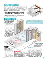
    2. All openings of a horizontal slide gate are guarded or screened from the bottom of the gate to a minimum of 6 feet  
   (1.83 m) above the ground to prevent a 2 ¼ inch (57.2 mm) diameter sphere from passing through the openings
    anywhere in the gate, and in that portion of the adjacent fence that the gate covers in the open position.
    3. All exposed pinch points are eliminated or guarded.
    4. Guarding is supplied for exposed rollers. 

 The operator is intended for installation only on gates used for vehicles. Pedestrians must be supplied with a separate  

  access opening. The pedestrian access opening shall be designed to promote pedestrian usage. Locate the gate such that  
  persons will not come in contact with the vehicular gate during the entire path of travel of the vehicular gate. 

 The gate must be installed in a location so that enough clearance is supplied between the gate and adjacent structures  

  when opening and closing to reduce the risk of entrapment. Swinging gates should not open into public access areas.

 The gate must be properly installed and work freely in both directions prior to the installation of the gate operator. Do not  

  over-tighten the operator clutch, pressure relief valve or reduce reversing sensitivity to compensate for a damaged gate.

 For gate operators utilizing Type D protection:

    1. The gate operator controls must be placed so that the user has full view of the gate area when the gate is moving.
    2. A warning placard shall be placed adjacent to the controls.
    3. An automatic closing device (such as a timer, loop sensor, or similar device) shall not be employed.
    4. No other activation device shall be connected.

 Controls intended for user activation must be located at least ten feet (10’) away from any moving part of the gate and  

  where the user is prevented from reaching over, under, around or through the gate to operate the controls. Outdoor or  
  easily accessible controls should have a security feature to prevent unauthorized use.

 The Stop and/or Reset button must be located in the line-of-sight of the gate. Activation of the reset control shall not   

  cause the operator to start.

 A minimum of two (2) WARNING SIGNS shall be installed, one on each side of the gate where easily visible.

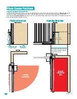
 For gate operators utilizing a non-contact sensor: 

    1. See the instructions on the placement of non-contact sensors for each type of application.
    2. Care shall be exercised to reduce the risk of nuisance tripping, such as when a vehicle trips the sensor while the gate  
      is still moving in the opening direction.
    3. One or more non-contact sensors shall be located where the risk of entrapment or obstruction exist, such as the  
      perimeter reachable by a moving gate or barrier.

ASTM F2200 Standard for Gate Construction

Содержание 6400 - UL 325 Class 1

Страница 1: ...M O D E L S E R IA L V O L T S P H A S E A M P S 6 0 H z M A X G A T E L O A D Do orKing Inc Inglew oo d CA Gate Operator and Control Box Mounting Vehicular Swing Gate Operator To wire this operator and complete the installation refer to a specific control box Wiring Owner s manual CLASS CERTIFIED TO CAN CSA C22 2 NO 247 CONFORMS TO ANSI UL 325 VEHICULAR GATE OPERATOR HP 53382 MODEL SERIAL VOLTS P...

Страница 2: ......

Страница 3: ...ing Inc makes no representations or warranties with respect to this manual This manual is copyrighted all rights reserved No portion of this manual may be copied reproduced translated or reduced to any electronic medium without prior written consent from DoorKing Inc Class of Operation Model 6400 UL 325 Class I Type of Gate Vehicular Swing Gates Only Gate Operator Voltage 24 VDC Current 3 Amps Mot...

Страница 4: ...es UL 325 Entrapment Protection Glossary Swing Gate Requirements Swing Gate Protection 1 3 3 3 4 5 6 7 8 INSTALLATION 9 9 10 11 12 13 14 15 15 16 17 18 Manual Key Release Installation of 6400 Drive Motor Orientation and Components Installation Mounting Control Box with Conduit Install Warning Signs In Ground Loops Photo Sensor Positions Accessory Items 6400 Primary Secondary 4302 Circuit Board Con...

Страница 5: ...ess opening shall be designed to promote pedestrian usage Locate the gate such that persons will not come in contact with the vehicular gate during the entire path of travel of the vehicular gate The gate must be installed in a location so that enough clearance is supplied between the gate and adjacent structures when opening and closing to reduce the risk of entrapment Swinging gates should not o...

Страница 6: ...d and maintained serious injuries or death can result Be sure that the installer has instructed you on the proper operation of the gate and gate operator system Be sure that the installer has trained you about the basic functions of the required reversing systems associated with your gate operating system and how to test them These include reversing loops inherent reversing system electric edges p...

Страница 7: ...c in which unauthorized access is prevented via supervision by security personnel This table illustrates the entrapment protection requirements for each of the four UL 325 classes A Inherent entrapment protection system B1 Provision for connection of or supplied with a non contact sensor photoelectric sensor or the equivalent When used as the PRIMARY device must be monitored B2 Provision for conne...

Страница 8: ...for vehicular traffic flow at entrances or exits to areas such as parking garages lots or toll areas VEHICULAR HORIZONTAL SLIDE GATE OPERATOR OR SYSTEM A vehicular gate operator or system that controls a gate which slides in a horizontal direction that is intended for use for vehicular entrance and exit to a drive parking lot or the like VEHICULAR SWING GATE OPERATOR OR SYSTEM A vehicular gate ope...

Страница 9: ...e vehicular gate ref UL325 56 8 4 b Not Allowed OK Closed Gates Gates shall have smooth bottom edges with vertical bottom edged protrusions not exceeding 0 50 inches ASTM F2200 4 3 If distance is greater than 4 inches entrapment protection for this area is required ASTM F2200 7 1 1 1 If distance is less than 16 inches entrapment protection in this area is required ASTM F2200 7 1 1 2 A B A B Closed...

Страница 10: ...tomatic Exit Loop Minimizes the potential of the gate closing when a vehicle is present Number and placement of loops is dependent on the application Reverse Loop Minimizes the potential of the gate closing when a vehicle is present Number and placement of loops is dependent on the application Optional will provide an open command to the gate operator s when a vehicle is exiting the property Provi...

Страница 11: ... UL 325 safety and ASTM F2200 construction standards The proper installation of the vehicular slide gate operator is an extremely important and integral part of the overall access control system Check all local building ordinances and building codes prior to installing this operator Be sure your installation is in compliance with local codes Hinges for the Gate Good hinges are essential for proper...

Страница 12: ...foundation box pivot point Good Soil Drainage Concrete Foundation Box Position and Installation Foundation Box Pivot Point 3 3 3 1 1 2 drainage pipe Not supplied Plumb Run 3 4 conduit with sweeps from foundation box to where control box will be mounted 2 5 8 foundation box pivot point Junction Box Sample Hinges Good Soil Drainage Concrete 6 Driveway Foundation Box Drain pipe can connect to an exis...

Страница 13: ... on the 6400 DO NOT weld gate frame to U Channel Protect the 2 release handles from welding sparks during welding Release Handle Foundation Box U Channel Dimensions After the foundation box has been mounted in concrete and the gate has been connected to it proceed to the next page to correctly orient drive motor and install components in the foundation box 15 3 4 Gate Frame U Channel D D 1 1 1 2 M...

Страница 14: ...te to be in the correct Open clockwise position Note Precise Final limit adjustments will be made when wiring the operator See the selected control box Wiring Owner s manual Open Gate Close Gate Drive Arm Limit Plate Limit Plate Limit Plate Open Limit Assembly Position 4 Slo Dwn Purple White 3 Limit Gray White Close Limit Assembly Position Purple White 4 Slo Dwn Gray White 3 Limit Close Limit Asse...

Страница 15: ...local building codes prior to installing any permanent wiring to ensure all wiring and connections comply with local electrical code requirements Position the desired control box on the wall close enough to the operator so the primary operator cable can be easily routed inside the box Make sure that the control box is mounted high enough off the ground that it will NOT come in contact with standin...

Страница 16: ...essary Low Voltage Primary Operator Secondary Operator Solar Power Flexible Conduit Low Voltage Low Voltage Low Voltage 3 4 conduit recommended Coaxial Cable Antenna Kit P N 1514 073 Sold separately Primary Operator Conduit From Secondary Operator if Installed See previous page Drain Pipe Solar Control Box DO NOT use a 12 volt solar panel Damage WILL occur One 24 V 10 watt panel required for 18 Am...

Страница 17: ...revent the gate from closing on a vehicle in these areas They will reverse the cycling of the gate while a vehicle is in or near the gate s swing pathway Loop Lead In Wires Low Voltage In Ground Loops Loop lead in wires are twisted approx 6 twists per foot in PVC conduit to the control box Install Warning Signs This DoorKing Swing Gate Operator is shipped with two warning signs The purpose of the ...

Страница 18: ...1 Typical 27 5 Maximum Opening Direction Side View Wall If this space is less than 16 inches secondary entrapment protection is required in this area Gate Frame Closed Opening Direction Photo Beam Potential Entrapment Area Top View Top View Secondary Entrapment Protection Device In addition to the inherent reversing sensor system the Model 6400 has a 6 pin UL 325 terminal for the connection of pho...

Страница 19: ... Model E3K R10K4 NR Loop Hardware DoorKing offers a complete line of loop components to complete your gate operator system See DoorKing s web site www doorking com See the free manual Loop and Loop Detectors Information PDF located at Doorking s technical web site www dkaccess com Magnetic Lock Magnetic Gate Lock Kit provides an excellent means to secure swing gates and is a fail safe device allow...

Страница 20: ...n Yellow Orange 1 7 6 5 4 3 2 1 2 3 4 5 6 7 8 9 10 11 12 13 14 15 16 17 18 19 20 1 7 6 5 4 3 2 Secondary Operator Primary Operator Important Secondary operator Motor wires Blue Brown MUST be reversed from the primary operator motor wires Blue wire 1 Brown wire 2 Orange wire 3 Red wire 4 Yellow wire 5 Green wire 6 Green Yellow wire 7 Brown wire 1 Blue wire 2 Orange wire 3 Red wire 4 Yellow wire 5 G...

Страница 21: ...6400 065 T 8 12 19 ...

Страница 22: ... Glasgow Avenue Inglewood California 90301 U S A Phone 310 645 0023 Fax 310 641 1586 6400 6400 6400 Gate Operator and Control Box Mounting Vehicular Swing Gate Operator To wire this operator and complete the installation refer to the specific control box Wiring Owner s manual 6400 065 T 8 12 ...

Отзывы: