


6400-065-T-8-12
14
Mounting Control Box Continued
Operators Conduit
Input Power
Conduit
Loops Conduit
Mounting Pole
Not Provided
Flexible Conduit
Junction
Boxes
Elbow
NO
Sweep
YES
Conduit
Solar Cabinet
Mounting Holes
and Conduit
Holes
3/4” Conduit
Knockouts
Mounting
Holes
Mounting Hole
3/4” Conduit
Knockouts
Ante
nna
Hole
Cabinet
Back
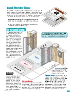
DoorKing offers a mounting
post kit (P/N 1000-045)
when no vertical surface is
available to mount the solar
control box cabinet to.
Cover
Mounti
ng Post
Mount to
Concrete
To attach post to concrete,
DoorKing recommends four
(4) 3/8” x 3” sleeve anchors
(not supplied). Do Not mount
post on asphalt.
Cabinet
Back
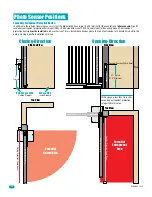
Loops
Typical conduit
configuration
(not supplied).
Remove fragile
components
from control
box to protect
them during
installation if
necessary.
Low
V
oltage
Primar
y Operator
Secondar
y Operator
Solar
Power
Flexible
Conduit
Low
V
oltage
Low
V
oltage
Low
V
oltage
3/4” conduit
recommended.
Coaxial
Cable
Antenna
Kit
P/N
1514-073
(Sold
separately)
Primary Operator Conduit
From Secondary Operator if Installed (See previous page)
Drain Pipe
Solar Control Box
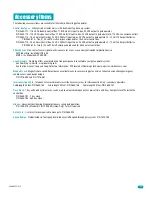
DO NOT
use a 12 volt solar panel. Damage WILL occur!!
•
One
24 V 10 watt panel
required for 18 Amp/Hr
batteries.
DO NOT USE
10 watt panel with the
35 Amp/Hr batteries.
•
One
24 V 20 watt panel
required for 35 Amp/Hr batteries.
DO NOT USE
20 watt panel with
the18 Amp/Hr batteries.
ONLY Mount One 24 Volt Solar Panel!
The 24 volt - 10 watt or 20 watt solar panel must be correctly installed for
the system to function correctly. See the solar control box Wiring/Owner’s
manual for more information about concerns, considerations and
recommendations for proper solar panel positioning and mounting.
24 Volt 10 Watt
Solar Panel
P/N 2000-077
24 Volt 20 Watt
Solar Panel
P/N 2000-076
Содержание 6400 - UL 325 Class 1
Страница 2: ......
Страница 21: ...6400 065 T 8 12 19 ...