background image

maIntenanCe

40

Kohler Engine

These engines are equipped with a replaceable, high 
density paper air cleaner element. Some engines 
are also equipped with an oiled, foam precleaner 
surrounding the paper element.
Check the air cleaner daily or before starting the 
engine. Check for a buildup of dirt and debris around 
the air cleaner system. Keep this area clean. Also 
check for loose or damaged components. replace all 
bent or damaged air cleaner components.

Servicing Precleaner

If so equipped, wash and re-oil the precleaner every 
25 hours of operation (more often under extremely 
dusty or dirty conditions). replace the precleaner 
annually, or every 100 hours.

open the door on the blower housing to access 

1. 

the air cleaner element and precleaner.
Unhook the latch and remove the air cleaner 

2. 

element assembly for servicing. make sure the 
base and the sealing areas are clean before 
reassembly.
Wash the precleaner in warm water with 

3. 

detergent. rinse the precleaner thoroughly until all 
traces of detergent are eliminated. Squeeze out 
excess water (do not wring). Allow the precleaner 
to air dry.
Saturate the precleaner with new engine oil. 

4. 

Squeeze out all excess oil.

Servicing Paper Element

Check the paper element every 50 hours of operation, 
(more often under extremely dusty or dirty conditions). 
Clean or replace the element as necessary. replace 
the air cleaner element annually, or every 100 hours.

remove the precleaner (if so equipped) from the 

1. 

paper element.
Gently tap the paper element to dislodge dirt. do 

2. 

not wash the paper element or use pressurized 
air, as this will damage the element. replace a 
dirty, bent, or damaged element with a new one. 
Handle the new element carefully; do not use if 
the sealing surfaces are bent or damaged.
Clean the air cleaner base as required and check 

3. 

condition.
reinstall the precleaner (if equipped) over the 

4. 

paper air cleaner element and install on the base. 
Secure with the latch.
Close and latch the door.

5. 

IMPORTANT INFORMATION

Operating the engine with loose or damaged 
air cleaner components could allow unfiltered 
air into the engine causing premature wear 
and failure.

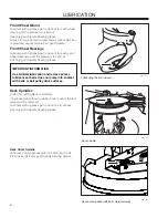
8058-028

1. air cleaner access door
2. air cleaner element
3. latch
4. precleaner (on some models)

Air filter cleaning and replacement

1

4

3

2

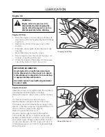
8058-029

Unlatch and remove element

Содержание 966038601

Страница 1: ...or Manual RAM 52ZT 966038601 RAM 48ZT 966495301 RAM 52ZT BF 966054301 RAM 48ZT BF 966495401 Please read the operator s manual carefully and make sure you understand the instructions before using the m...

Страница 2: ...2009 HTC All rights reserved Beatrice NE Printed in U S A...

Страница 3: ...ransport 33 Bypass Linkages 33 Maintenance 34 Maintenance Schedule 34 Battery 36 Ignition System 37 Safety System 37 Engine Cooling Air Intake 38 Throttle Cable 38 Choke Cable 38 Air Filter 39 Briggs...

Страница 4: ...d mind and body and must not be under the influence of any mind altering substance WARNING Engine exhaust some of its constituents and certain vehicle components contain or emit chemicals known to the...

Страница 5: ...g equipment and ensure that the machine is well anchored DO NOT operate this machine on public roadways Towing If machine is equipped with a tow hitch use extreme caution when towing Never allow child...

Страница 6: ...ollowing professional Manufacturing Number The machine s manufacturing number can be found on the printed plate affixed to the right in the engine compartment Stated on the plate from the top are The...

Страница 7: ...for misuse or misassembly IMPORTANT INFORMATION Xxxx xxxxxx xxxxx xxxx xxxxxxxxx xxxxxx xxxxxxxxx xx xxxxxxxx xxxx xxxxxx Reverse Neutral Fast Slow Choke Fuel Warning Parking Brake CE conformity Warn...

Страница 8: ...no greater Manual performing any the machine than 10 maintenance or repair work Whole body Severing of fingers Do not open or Careful backing up Careful going exposure to and toes remove safety watch...

Страница 9: ...unless absolutely necessary Always look down and behind before and while backing Never direct discharged material toward anyone Avoid discharging material against a wall or obstruction Material may ri...

Страница 10: ...ge 60 years and above are involved in a large percentage of riding mower related injuries These operators should evaluate their ability to operate the riding mower safely enough to protect themselves...

Страница 11: ...are a major factor related to loss of control and tip over accidents which can result in severe injury or death Operation on all slopes requires extra caution If you cannot back up the slope or if you...

Страница 12: ...he watchful care of a responsible adult other than the operator Be alert and turn machine off if a child enters the area Before and while backing look behind and down for small children Never carry ch...

Страница 13: ...round If this is not possible refuel such equipment with a portable container rather than from a gasoline dispenser nozzle Keep the nozzle in contact with the rim of the fuel tank or container opening...

Страница 14: ...ity regularly Adjust and service as necessary Maintain or replace safety and instruction labels as necessary Do not modify safety equipment Check regularly to be sure it works properly The machine mus...

Страница 15: ...eas when higher quality mowing is desired WARNING Avoid electrical sparking and its consequences by the following routines Sparking can occur when working with the battery and the heavy cables of the...

Страница 16: ...hand Customer Responsibilities Read and observe the safety rules Follow a regular schedule in maintaining caring for and using your mower Follow the instructions under Maintenance and Storage section...

Страница 17: ...es 9 Fuel shut off valve 10 Fuel tank cap 11 Parking brake 12 12 belt driven hydraulic pumps which in turn drive a hydraulic motor for each drive wheel Using the left and right steering controls the f...

Страница 18: ...ntrol forward from its neutral position The rotation direction when zero turning is determined by which steering control is moved backward behind the neutral position If the left steering control is p...

Страница 19: ...f the blades assuming the blade switch is pulled out see Engaging the Mower Deck In order to increase or decrease the engine speed the control is moved forward or back respectively Avoid idling the en...

Страница 20: ...g time It will flash CHG OIL Change Oil at 50 hour intervals The flash duration is one hour before and one hour after the interval The CHG OIL icon will come on and shut off automatically The hour met...

Страница 21: ...ATION The machine must stand absolutely still when applying the parking brake Always set the parking brake before dismounting Release the parking brake before moving the mower Parking Brake The parkin...

Страница 22: ...Do not overfill Wipe off any spilled oil or fuel Do not store spill or use gasoline near an open flame WARNING The engine and the exhaust system become very hot during operation Risk for burns if tou...

Страница 23: ...under its own power the operator must be in the seat start engine see Before Starting in Operation section adjust engine speed to idle disengage parking brake do not engage blades IMPORTANT INFORMATIO...

Страница 24: ...switch for engaging the mower blades must be depressed The parking brake must be on Both steering controls must be in the locked outer neutral position Starting the Engine Sit on the seat Raise the mo...

Страница 25: ...ward to the locked outer neutral position 8050 817 1 Set the throttle Move the throttle to the middle position If the engine is cold push the choke lever to ON 8061 020 Place controls in neutral locke...

Страница 26: ...arts immediately release the ignition key back to the run position IMPORTANT INFORMATION Do not run the starter for more than 5 seconds each time If the engine does not start wait about 10 seconds bef...

Страница 27: ...loading it too heavily USE FULL THROTTLE WHEN MOWING no choke 8050 817 1 Release choke 8050 817 1 Set engine speed WARNING Engine exhaust and certain vehicle components contain or emit chemicals cons...

Страница 28: ...aking care not to short against chassis Connect one end of the BLACK cable to the 2 NEGATIVE terminal of the fully charged battery Connect the other end of the BLACK cable 3 to a good CHASSIS GROUND o...

Страница 29: ...i scalp rollers should be evenly adjusted 8058 020 Released parking brake WARNING Ensure that no one is near mower when engaging blade switch Make sure the work area is free from objects that could be...

Страница 30: ...fully moving the other steering control forward from its neutral position 8050 781 Set blade engagement and throttle control IMPORTANT INFORMATION Control levers return to neutral when released This m...

Страница 31: ...awn becomes more even and the grass clippings more evenly distributed over the mown area The total time taken is not increased as a higher operating speed can be used without poor mowing results Avoid...

Страница 32: ...ower deck by depressing the 1 blade switch Raise the mower deck by depressing the button 2 on the lift lever and pulling backward to the transport position When the machine is standing still activate...

Страница 33: ...and out of the 2 keyhole slots Release the levers with the head outside the frame and held in the bypass position To reengage the ZT 2800 to drive reverse the 3 above procedure Load the machine into t...

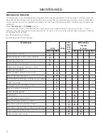
Страница 34: ...4 Performed by authorized service workshop Described in this manual Not described in this manual Maintenance At least once each year Maintenance Wkly interval Daily in hours Before After 25 50 100 30...

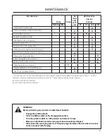
Страница 35: ...ing and replacement are required more often 3 Performed by authorized service workshop Described in this manual Not described in this manual Maintenance At least once each year Maintenance Wkly interv...

Страница 36: ...old battery Reinstall battery hold down and secure with 7 nuts removed in Step 5 First connect RED battery cable to positive 8 battery terminal with hex bolt and hex nut Connect BLACK grounding cable...

Страница 37: ...ystem The machine is equipped with a safety system that prevents starting or driving under the following conditions The engine can only be started when The mower deck is disengaged The steering contro...

Страница 38: ...sition 2 Check that the throttle cable is mounted in the correct hole in the lower lever see illustration 3 Push the throttle cable s outer casing as far to the right as possible and tighten the clamp...

Страница 39: ...nd the exhaust system become very hot during operation Risk for burns if touched Allow engine and exhaust system to cool at least two 2 minutes Remove the foam filter precleaner Clean the 3 foam filte...

Страница 40: ...o not wring Allow the precleaner to air dry Saturate the precleaner with new engine oil 4 Squeeze out all excess oil Servicing Paper Element Check the paper element every 50 hours of operation more of...

Страница 41: ...4 filter with the FLOW arrow pointing up toward the fuel pump If necessary a soap solution can be applied to the filter ends to ease mounting Move the hose clamps back toward the filter 5 8011 468 Fue...

Страница 42: ...ormal operation The belts are not adjustable Replace belts if they begin to slip from wear Deck Belt Removal Park on a level surface Apply parking brake 1 Lower the deck into the lowest cutting positi...

Страница 43: ...y twist Correct as needed Replace belt shields on both mandrel housings 7 and secure with fasteners 8011 764 Clutch pulley 1 Deck belt 2 Belt routing deck belt 1 2 Pump Belt Replacing pump belt Park t...

Страница 44: ...Blade attachment 1 2 3 Cutting Blades In order to attain the best mowing effect it is important that the blades are well sharpened and not damaged Bent or cracked blades or blades with large nicks sho...

Страница 45: ...ment is the same If adjustment is required with a or adjustable wrench turn the lift link adjustment nuts on either side counter clockwise to lower or clockwise to raise Adjust until both side to side...

Страница 46: ...MPORTANT INFORMATION Adjust anti scalp rollers with the mower on a flat level surface The anti scalp rollers can be set in three positions Upper position 1 to 2 38 to 64 mm grass Middle position 2 to...

Страница 47: ...d any type of tire liner or foam fill material to the tires Excessive loads created by foam filled tires will cause premature failures Only use O E M specified tires 8050 831 Clean regularly IMPORTANT...

Страница 48: ...ion Reinstall the retaining clip and recheck gap between rod swivel pin and brake rod washer Repeat the procedure on the other EZT Tracking Adjustment If the mower is not tracking straight check the a...

Страница 49: ...hould be lubricated twice weekly Lubrication Schedule Wipe away excess grease after lubrication It is important to avoid getting lubricant on the belts or the drive surfaces on the belt pulleys Should...

Страница 50: ...grease 8011 731 Lubricating the front wheels 8011 732 Deck spindle IMPORTANT INFORMATION Use minimal lubrication and remove excess lubricant so that is does not come into contact with belts or belt p...

Страница 51: ...hanging the oil filter WARNING Engine oil can be very hot if it is drained directly after stopping the engine Allow the engine to cool to a safe temperature before draining Engine Oil Levels Check the...

Страница 52: ...l drain valve is located on the left side of the unit below the oil filter Place the machine on a flat surface Place a container under the engine where the oil drain valve exits Remove the valve cap A...

Страница 53: ...d Torque screws to 5 65 in lbs each Repeat steps on the opposite side 6 Drain old oil filters of all free flowing oil prior to 7 disposal Place used oil in appropriate containers and dispose of it in...

Страница 54: ...ing at fast idle slowly move the steering control in both forward and reverse directions 5 or 6 times As air is purged from the unit the oil level will drop With the bypass valve closed and the engine...

Страница 55: ...r contact of the battery terminal cable connections Blown fuse Fault in the starter safety circuit See Safety System in the Maintenance section Engine runs rough Faulty carburetor Choke control is pul...

Страница 56: ...brake on Bypass valve on pump open Drive belt for the transmission slack or has come off Air trapped in hydraulic system Mower deck not engaging Drive belt for the mower deck has come loose Contact fo...

Страница 57: ...l tanks or add a fuel stabilizer Start 4 the engine and allow it to run until the carburetor is drained of fuel or the stabilizer has reached the carburetor Remove the spark plug and pour about a 5 ta...

Страница 58: ...schematics 58...

Страница 59: ...coarse thread ft lbs ft lbs Nm ft lbs Nm ft lbs Nm 9 12 13 18 5 16 18 24 28 38 24 33 3 8 31 42 46 62 40 54 7 16 50 68 75 108 75 102 115 156 9 16 110 150 165 224 5 8 150 203 225 305 250 339 370 502 7 8...

Страница 60: ...MTBE 15 Fuel tank capacity 4 5 gallon 15 1 liters 4 5 gallons 15 1 liters Spark plugs gap Champion XC12YC 030 0 75 mm NGK BPR4ES 030 0 75 mm Cooling Air cooled Air cooled Air filter Standard Standard...

Страница 61: ...s Yes Hour Meter Standard Standard Blade Engagement Electromagnetic clutch Electromagnetic clutch Deck Construction 11 gauge w 10 gauge skirts 11 gauge w 10 gauge skirts Productivity 2 88 acres h 1165...

Страница 62: ...s This is also applicable to special requirements for any of the states California emission rules etc Do not remove any of these labels Certificates can also be supplied with the machine at delivery o...

Страница 63: ...ranty must be accomplished by authorized Dixon dealers and in accordance with Dixon warranty policy and allowances All warranty claims must be submitted to Dixon for approval 4 Warranty labor reimburs...

Страница 64: ...mower deck adjustment 11 Check The safety switch for the parking brake The safety switch for the mower deck The safety switch in the seat The safety switch in the steering controls Parking brake funct...

Страница 65: ...5 8 Hours 1 Change engine oil 25 Hour Service 1 Check the engine air filter 2 Sharpen Replace mower blades if required 3 Check the tire pressures 4 Check battery with cables 5 Lubricate according to...

Страница 66: ...engine oil 4 Lubricate according to lubrication chart 5 Check adjust the parking brake 6 Change hydraulic pump oil and filter 100 Hour Service 1 Perform the 25 hour service 2 Perform the 50 hour serv...

Страница 67: ...ngine valve clearance 7 Replace the air cleaner s prefilter foam At Least Once Each Year 1 Clean the engine s cooling air intake 25 hours 2 Replace the air cleaner s pre filter foam 300 hours 3 Replac...

Страница 68: ...68 SERVICE JOURNAL Action Date mtr reading stamp sign...

Страница 69: ...69 SERVICE JOURNAL Action Date mtr reading stamp sign...

Страница 70: ...70 SERVICE JOURNAL Action Date mtr reading stamp sign...

Страница 71: ......

Страница 72: ...P N 115 294527R1 09 21 09...

Отзывы: