

© 2012 Directed. All rights Reserved.
1
Quick Reference Install Guide
VSM50BT/DSM50BT/ASM50BT
BLUETOOTH
Module
®
®
BLUETOOTH
Module
®
®
Introduction
This product can be used as a standalone product or in conjunction with an exist-
ing Directed product. It is compatible with most Directed Security, Remote Start and
hybrid systems. This guide also assumes that the user has already downloaded the
bluetooth app to their smartphone, its required for installation testing.
First determine whether the system is being installed as a standalone or being con-
nected to an existing product. If being used with an existing product, determine
whether the 8210 RF adapter kit is also required. If the existing product uses 4-pin RF
connectors, you will need the 8210 RF adapter kit. Start with the following installa-
tion procedure then go to the appropriate standalone or existing product procedure
and follow the instructions provided.
Installation Procedure
First, determine an appropriate location for the DSM50BT module such as along the
dashboard. It is recommended that you mount the module in the highest unobstructed
position possible. This offers the best signal reception. The harness length and wiring
route through the dashboard may also dictate the position chosen.
Note:
Do not extend harnesses beyond the manufactured length.
The DSM50BT module comes with a mounting bracket and hardware. Mount this
bracket first using the provided hardware and insert the module into it.
Note:
Caution should be taken when mounting the bracket due to possible interfer-
ence with existing harnesses or equipment around or behind the mounting position.
As a Standalone
1. Connect the unterminated end of the H1 main harness first using the following
wiring table and diagram.
2. Connect the H1 connector end to the middle port (white)of the module.
H1 6-pin Harness
Pin #
Wire Color
Connection/Description
1
Red
+12V
2
Black
GND
3
Green
Lock (output 1)
4
Blue
Unlock (output 2)
5
White
Start/Stop (output 4)
6
Pink
Trunk (output 3)
Wiring Diagram for Standalone
CPU1
Green White Black
Green White Black
Directed
Control Module
Control Center
Bluetooth Control Module
Programming
LED
Learn
Button
Control
Button
Status
LED
Pair
Button
Note: Actual Control Module may differ
to the example shown in diagram.
Arrow to Control Module does not reflect
the actual location of this connection
Note: Actual Control Center
may differ to the example
shown in diagram
H1 Main Harness
(see wiring table)
Bluetooth Control Module
Side view, Standalone application
H1 Main Harness
(see wiring table)
Not used
Not used
With an Existing Product
1. Unplug the existing control center (IVU) cable.
2. Connect the H2 harness from the green port of the DSM50BT module to the
control center (see note).
3. Now connect the disconnected end of the control center cable to the black
porton the module (see note).
4. Terminate only the required loose wires of the H1 main harness first using the
following wiring table and diagram.
5. Connect the H1 connector end to the white port of the DSM50BT module .
Note
: If the supplied cables do not fit the Directed system, then the system requires
the 8210 RF adapter kit which is sold separately.
H1 6-pin Harness
Pin #
Wire Color
Connection/Description
1
Red
+12V
2
Black
GND
3
Green
Not Connected
4
Blue
Not Connected
5
White
Not Connected
6
Pink
Not Connected
Note
: Cut unused wires back to harness sleeve to prevent possible shorts.
Wiring Diagram for use with Existing Product using 6-pin RF connectors
CPU1
Green White Black
Green White Black
Directed
Control Module
Control Center
Bluetooth Control Module
Programming
LED
Learn
Button
Control
Button
Status
LED
Pair
Button
Note: Actual Control Module may differ
to the example shown in diagram.
Arrow to Control Module does not reflect
the actual location of this connection
Note: Actual Control Center
may differ to the example
shown in diagram
H1 Main Harness
(see wiring table)
Bluetooth Control Module
Side view, Standalone application
H1 Main Harness
(see wiring table)
Not used
Not used
ON
89
7
6
5
4
3
2
1
Antenna/RF
AstroStart Remote Starter
AutoStart Remote Starter
Antenna/RF
Antenna/RF
Remote Start or Security Systems
depending on model.
White
White
Green
Black
Green
White
White
Green
AutoStart
Antenna
A
str
oS
tar
t
A
ntenna
Viper
, P
ython
Cliff
or
d, XL202
A
ntenna
Directed SmartStart
BLuetooth Control Module
Black
Green
XL202: Range Extender
Antenna/RF
D2D Port
LED
Programming
Button
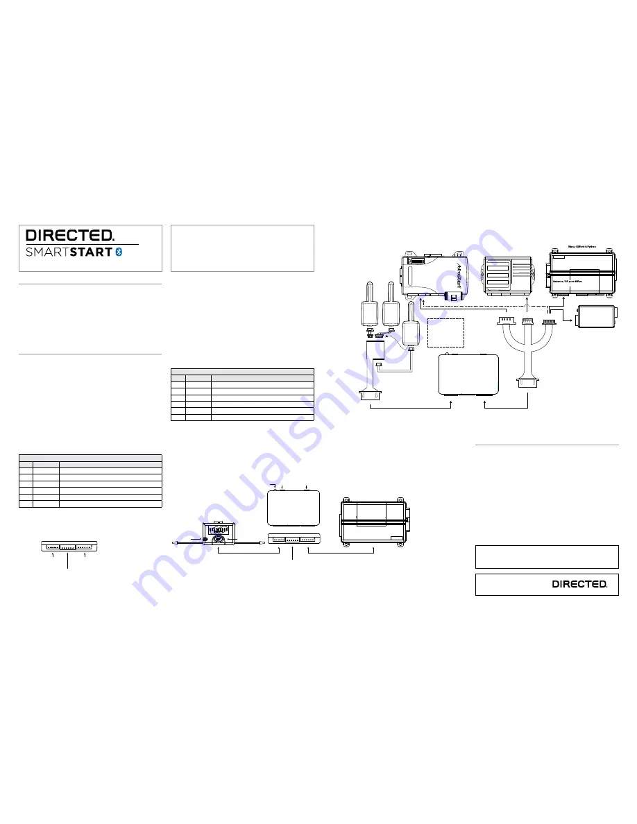
AstroStart connections:
The green connector on
8210 RF Adapter harness
connect only to AstroStart
Remote Starter XRT, model
RSS-2524. Other models
connect to the large white
4-pin connector.
Note: Actual Antenna
Control Center may
differ to the example
shown in diagram.
Original antenna harness
must be used to connect
the antenna in the 8210
Antenna Adapter.
8210 - PKE and SmartStart
Bluetooth RF Harness Adapter
Kit
8210 - PKE and SmartStart
Bluetooth RF Harness Adapter
Kit
Note: Actual modules may differ
from those shown in diagram and
arrows may not reflect actual
connection point.
Optional 8210 RF adapter wiring diagram (if required).
Additional information can be
found at:
www.directechs.com
Notes:
Bluetooth response time can vary depending on range and proximity
to the vehicle. Operating temperature range: -30°C to + 70°C.
To Pair the Smartphone to the DSM50BT
module:
1. Press and hold the Pair button on the module for ten seconds, continue holding
until the red LED (approximately five seconds) changes to solid blue.
2. Release the Pair button. The blue LED begins flashing to indicate Pairing mode.
Note
: Perform the next steps within sixty seconds or the unit will exit pairing
mode.
3. Turn on the Bluetooth feature of your cellular device, enter the pairing menu
and select “SmartStartBT- ####” from the available devices list. Each Directed
DSM50BT device has a unique ID.
4. The Blue LED begins flashing rapidly to indicate successful pairing and connec-
tion between the smartphone and Directed DSM50BT device.
5. The DSM50BT automatically exits pairing mode when it connects to the smart-
phone, but you can also exit manually at any time by pressing and releasing
the Pair button.
Note
: The system can only be connected with one smartphone at a time. If you need
to pair a second phone, turn off Bluetooth on the first phone or move it out of range
before you attempt to pair and connect the second phone.


