www.glendimplex.de
DOK4x HOIAO FxDEN · FD 0001
11
Air-to-water heat pump M Flex
English
6 Assembly / connection
6.1 Assembly of the refrigerant line
and electric wire
The refrigerant lines and electric wires for connecting the in-
door unit with the outdoor unit must be ordered separately as
accessories.
To route the connection wires, create wall openings at suitable
points. The wall opening must be protected from water pene-
tration according to the local conditions.
The wall openings should be sealed again correctly once the
routing work is complete. (For connecting the electric wire, see
cap. 6.6 on page 14, for connecting the refrigerant line, see
cap. 6.8 on page 19).
6.2 Condensate drain
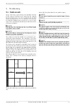
Condensate that forms during operation must be drained off
frost free. To ensure proper drainage, the outdoor unit must be
mounted horizontally.
The condensate tray offers various options for the condensate
drain:
Foundation covered with gravel. The leaching should be
min. 1.5 l per kW of heat output per day, and the diameter
of the drain pipe should be at least 50 mm.
Channel into a waste water, rain water or drainage channel
If the condensate drain is installed at risk from frost, it must be
protected from freezing with a condensate drain heater, which
is available as a special accessory.
The connection takes place in the outdoor unit and must take
place in accordance with the electrical documentation.
HINWEIS
ºº
º
ºº
º
NOTE
The frost line can vary according to the climatic region. The
regulations of the countries in question must be observed.
6.3 Connection on heating side
Before connecting the heating system to the heat pump, the
heating system must be flushed to remove any impurities, resi-
due from sealants, etc. Any accumulation of deposits in the liq-
uefier may cause the heat pump to completely break down.
A purging option must be arranged directly upstream and
downstream of the indoor unit.
Once the heat pump has been connected to the heating sys-
tem, it must be filled, purged and pressure-tested.
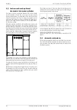
When doing so, it must be ensured that all heating circuits and
isolating valves are open and that the 3-way reversing valve is in
heating operation (pos. 1 factory default). Fill the heating sys-
tem at the fill and drain cock (pos. 2) until system pressure (ap-
prox. 1.5 bar) is reached. A suitable fill hose with a pressure
gauge should be used. When doing so, check all connections
and the entire heating system for leakages. The heating system
should be purged at the highest point (pos. 3, e.g. radiator, heat
pumps connection).
After all of the air has been purged, the indoor unit must be
purged on the domestic hot water cylinder (if present), on the
electric auxiliary heating (pos. 4), buffer tank (pos. 5), dirt filter
(pos. 6) and plate heat exchanger (pos. 7) until the heating
water also exits free of bubbles here.
If the power supply is connected, the reversing valve can be
switched for more effective purging on the touch display in the
installer level under Service and Analytics
Control functions
pumps. The generator pump M16 can also be activated for ad-
ditional support.
Finally, close the fill and drain cock, check the system pressure
and top up if necessary.
3
3
3
3
2
4
5
1
6
7
Содержание M Flex Air
Страница 2: ......
Страница 37: ...www glendimplex de DOK4x HOIAO FxDEN FD 0001 35 Air to water heat pump M Flex English...
Страница 38: ...36 DOK4x HOIAO FxDEN FD 0001 www glendimplex de English Air to water heat pump M Flex...
Страница 39: ...www glendimplex de DOK4x HOIAO FxDEN FD 0001 37 Air to water heat pump M Flex English...


