Dimplex DS5603 Скачать руководство пользователя страница 3


1

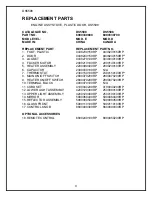
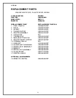
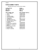
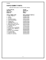
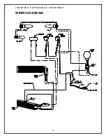
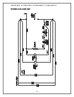
DS5598, DS5603, DS5804 


NOTE 

A 15amp, 120 volt circuit is required.  A dedicated circuit is preferred but not essential in 
all cases.  A dedicated circuit will be required if, after installation, the circuit breaker trips 
or fuse blows on a regular basis when the heater is operating.  Additional appliances on 
the same circuit may exceed the current rating of the circuit breaker. 


WARNING 

Ensure the power cord is not installed so that it is pinched or against a sharp edge and 
ensure that the power cord is stored or secured to avoid tripping or snagging to reduce 
the risk of fire, electric shock or injury to persons.


Construction and electrical outlet wiring must comply with local building codes and other 
applicable regulations to reduce the risk of fire, electric shock and injury to persons.


Do not attempt to wire your own new outlets or circuits.  To reduce the risk of fire, 
electric shock or injury to persons, always use a licensed electrician. 


STOVE INSTALLATION


1.  Make sure the units MAIN ON/OFF switch is switched OFF (refer to operating 

instruction section). 


2.  Plug the unit into a 15Amp/120volt outlet.  If the cord does not reach, you may use 

an extension cord rated for a minimum of 1875 watts. 
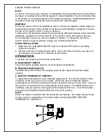
 

OPERATION


To access the controls go to the back of the Stove. 


A.


MAIN ON/OFF SWITCH 


The on/off switch supplies power to all unit functions (heat/flame) 


B. HEATER ON/OFF SWITCH  

The HEATER ON/OFF SWITCH supplies power to the heater fan and the heater 
element. 


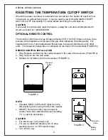
C. HEATER THERMOSTAT CONTROL 

To adjust the temperature to your individual requirements, turn the thermostat control 
clockwise all the way to turn on the heater.  When the room reached the desired 
temperature, turn the thermostat knob counter clockwise until you hear a click.  Leave in 
this position to maintain the room temperature at this setting.  For additional heat, turn 
clockwise until you hear the click again and the heater will turn on.  To turn the heater 
off, switch the HEATER ON/OFF SWITCH to the OFF position.


NOTE 

When the heater is switched ON, the heater fan will operate.  The heater element may 
or may not be on, depending on the thermostat control setting (SEE “HEATER 
THERMOSTAT CONTROL”). 


Содержание DS5603

Страница 1: ...PARTS SERVICE MANUAL FOR THE 20 STOVE MODEL NUMBER DS5598 DS5603 DS5804 ...

Страница 2: ... DIAGRAM PAGE 9 LIGHT BULB REPLACEMENT PAGE 11 MAIN ON OFF SWITCH REPLACEMENT PAGE 13 FLAME MOTOR FLAME ROD REPLACEMENT PAGE 14 HEATER ON OFF SWITCH REPLACEMENT PAGE 16 HEATER ASSEMBLY REPLACEMENT PAGE 17 HEATER THERMOSTAT CONTROL REPLACEMENT PAGE 18 POWER CORD REPLACEMENT PAGE 19 ...

Страница 3: ... sure the units MAIN ON OFF switch is switched OFF refer to operating instruction section 2 Plug the unit into a 15Amp 120volt outlet If the cord does not reach you may use an extension cord rated for a minimum of 1875 watts OPERATION To access the controls go to the back of the Stove A MAIN ON OFF SWITCH The on off switch supplies power to all unit functions heat flame B HEATER ON OFF SWITCH The ...

Страница 4: ...ng walls It is supplied with one of 243 independent frequencies to prevent interference with other units The frequency designation is indicated on the back of the transmitter FIGURE 3 REMOTE CONTROL INSTALLATION 1 Plug fireplace cordset into the outlet located on the side of the receiver FIGURE 2 2 Plug receiver into the wall outlet 3 Install a 9 volt battery into the transmitter FIGURE 3 NOTE Fir...

Страница 5: ...04 16 4 2 2 16 5 9 16 1 3 12 DS5603 Top Panel DS5804 Top Panel DS5598 Top Panel DS5603 Door Assembly DS5603 Side Panel DS5804 Door Assembly DS5804 Side Panel DS5598 Door Assembly DS5598 Side Panel 2 13 14 6 10 17 8 7 11 15 ...

Страница 6: ...P 2000230100RP 6 CAPACITOR 2300030100RP N A 7 THERMOSTAT 2300150100RP 2300150100RP 8 MAIN ON OFF SWITCH 2800070200RP 2800070200RP 9 HEATER ON OFF SWITCH 2800070200RP 2800070200RP 10 TERMINAL BLOCK 4000070100RP N A 11 CORD SET 4100040200RP 4100040200RP 12 LOWER LIGHT ASSEMBLY 4200120300RP 2500080100RP 13 UPPER LIGHT ASSEMBLY 4200120400RP 2500100100RP 14 MIRROR 5900060400RP 5900060400RP 15 REFLECTOR...

Страница 7: ...R MOTOR 2000140100RP 5 HEATER ASSEMBLY 6902410100RP 6 CAPACITOR N A 7 THERMOSTAT 2300150100RP 8 MAIN ON OFF SWITCH 2800070200RP 9 HEATER ON OFF SWITCH 2800070200RP 10 TERMINAL BLOCK N A 11 CORD SET 4100040200RP 12 LOWER LIGHT ASSEMBLY 2500080100RP 13 UPPER LIGHT ASSEMBLY 2500100100RP 14 MIRROR 5900060400RP 15 REFLECTOR ASSEMBLY 5900080500RP 16 GLASS FRONT 5900110100RP 17 CONTROL KNOB 8800000300RP ...

Страница 8: ...2200490400RP 2000230100RP 6 CAPACITOR 2300030100RP N A 7 THERMOSTAT 2300150100RP 2300150100RP 8 MAIN ON OFF SWITCH 2800070200RP 2800070200RP 9 HEATER ON OFF SWITCH 2800070200RP 2800070200RP 10 TERMINAL BLOCK 4000070100RP N A 11 CORD SET 4100040200RP 4100040200RP 12 LOWER LIGHT ASSEMBLY 4200120300RP 2500080100RP 13 UPPER LIGHT ASSEMBLY 4200120400RP 2500100100RP 14 MIRROR 5900060400RP 5900060400RP 1...

Страница 9: ...RP 4 FLICKER MOTOR 2000140100RP 5 HEATER ASSEMBLY 6902410100RP 6 CAPACITOR N A 7 THERMOSTAT 2300150100RP 8 MAIN ON OFF SWITCH 2800070200RP 9 HEATER ON OFF SWITCH 2800070200RP 10 TERMINAL BLOCK N A 11 CORD SET 4100040200RP 12 LOWER LIGHT ASSEMBLY 2500080100RP 13 UPPER LIGHT ASSEMBLY 2500100100RP 14 MIRROR 5900060400RP 15 REFLECTOR ASSEMBLY 5900080500RP 16 GLASS FRONT 5900360100RP 17 CONTROL KNOB 88...

Страница 10: ...ER MOTOR 2000210100RP 5 HEATER ASSEMBLY 2200490400RP 6 CAPACITOR 2300030100RP 7 THERMOSTAT 2300150100RP 8 MAIN ON OFF SWITCH 2800070200RP 9 HEATER ON OFF SWITCH 2800070200RP 10 TERMINAL BLOCK 4000070100RP 11 CORD SET 4100040200RP 12 LOWER LIGHT ASSEMBLY 4200120300RP 13 UPPER LIGHT ASSEMBLY 4200120400RP 14 MIRROR 5900060400RP 15 REFLECTOR ASSEMBLY 5900080500RP 16 GLASS FRONT 5900400100RP 17 CONTROL...

Страница 11: ...9 DS5598 MOD E DS5603 MOD E DS5804 MOD E WIRING DIAGRAM ...

Страница 12: ...10 DS5598 MOD D DS5603 MOD D DS5598 MOD C DS5603 MOD C WIRING DIAGRAM ...

Страница 13: ...s the log set exterior and two bulbs under the log set which generate the flames and embers It is a good idea to replace all of the light bulbs at one time if they are close to the end of their rated life Group replacement will reduce the number of times you need to open the unit to replace the light bulbs TO REPLACE UPPER LIGHT BULB 1 Open door by pulling the handle 2 Locate the upper bulb bracke...

Страница 14: ...t is a good idea to replace all of the light bulbs at one time if they are close to the end of their rated life Group replacement will reduce the number of times you need to open the unit to replace the light bulbs TO REPLACE LOWER LIGHT BULBS 1 Open door by pulling the handle 2 Remove the screw from the logset located in the center of the emberbed and remove the logset from the unit 3 Locate and ...

Страница 15: ...emove the rear legs 4 Remove the rear cover retaining screw located at the lower center of the rear cover 5 Slide the rear cover down 4 to 6 inches and gently pull the cover up from both the top and bottom bowing it slightly and remove it from its mounting slot When the cover is removed place beside the stove being careful not to damage any of the wiring 6 Locate the main on off switch mounted on ...

Страница 16: ... mounting slot When the cover is removed place beside the stove being careful not to damage any of the wiring 6 Locate the flame motor and flame rod assembly and remove the wiring clips and connections noting their original locations 7 Remove the mounting bracket screws on the flame motor side only and pull the assembly out of the other mounting bracket NOTE When removing the flame motor some dama...

Страница 17: ...avoid accidental burning of skin Disconnect power before attempting any maintenance or cleaning to reduce the risk of electric shock or damage to persons TO REPLACE FLAME MOTOR FLAME ROD 11 Properly orientate the flame motor and connect all of the wiring clips connections in their original locations 12 Reassemble in the reverse order as above ...

Страница 18: ...emove the rear legs 4 Remove the rear cover retaining screw located at the lower center of the rear cover 5 Slide the rear cover down 4 to 6 inches and gently pull the cover up from both the top and bottom bowing it slightly and remove it from its mounting slot When the cover is removed place beside the stove being careful not to damage any of the wiring 6 Locate the heater on off switch mounted o...

Страница 19: ...he front door closed gently place the stove door side up on a flat surface 3 Remove the heater assembly retaining screws located on the bottom of the stove with a screwdriver 4 Lower the heater assembly off of the bottom of the stove being careful not to damage any of the wiring 5 Disconnect the wiring clips and connections noting their original locations 6 Remove the heater assembly mounting scre...

Страница 20: ...ar cover retaining screw located at the lower center of the rear cover 5 Slide the rear cover down 4 to 6 inches and gently pull the cover up from both the top and bottom bowing it slightly and remove it from its mounting slot When the cover is removed place beside the stove being careful not to damage any of the wiring 6 Locate the heater thermostat control mounted on the rear cover and disconnec...

Страница 21: ...bowing it slightly and remove it from its mounting slot When the cover is removed place beside the stove being careful not to damage any of the wiring 6 Locate and disconnect the power cord wiring connections noting their original locations 7 Remove the heater cover retaining screws located on the bottom of the stove with a screwdriver 8 Lower the heater cover off of the bottom of the stove being ...

Отзывы: