


10
www.dimplex.com
Flicker Motor Replacement
Tools Required:
Phillips head screwdriver
Pliers
Side cutters
WARNING:
If the firebox was operating prior to
servicing, allow at least 10 minutes for the heating
elements to cool off to avoid accidental burning of skin.
WARNING:
Disconnect power before attempting any
maintenance to reduce the risk of electric shock or injury to
persons.
1. Follow the instructions for accessing the bottom
components on pages 8-9.
2. Remove the right side flicker rod retaining bracket by
unscrewing the two corresponding screws on the back
of the firebox. (Figure 5)
3. Pull the flicker motor out from the rubber coupling
attached to the flicker rod.
4. Remove the two screws that affix the flicker motor to
the bracket.
5. Cut the five wires as close as possible to the flicker
motor.
6. Cut wire leads from the new flicker motor to 3 1/2
inches long.
7. Using one of the supplied wire connectors, connect the
yellow wire from the new flicker motor with the yellow
wire cut from the old flicker motor.
8. Secure the wire connector by crimping the 3M symbol
with pliers. Pull on both wires to ensure a strong
connection.
9. Repeat the process for the 4 remaining wires, ensuring
that all wires are paired by colour in each connector.
10. Attach new flicker motor to the retaining bracket.
11. Insert stem from flicker rod into the rubber grommet.
12. Reattach the flicker rod retaining bracket.
13. Reassemble the firebox.
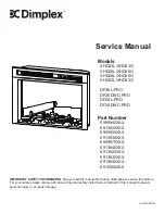
Remove this bracket when
changing flicker motor
Remove this bracket when
changing flicker rod
Media bed/Log
set screws
Flame screen retaining
bracket screws
Heater assembly screws
Flicker Rod Replacement
Tools Required:
Phillips head screwdriver
WARNING:
If the firebox was operating prior to
servicing, allow at least 10 minutes for the heating
elements to cool off to avoid accidental burning of skin.
WARNING:
Disconnect power before attempting any
maintenance to reduce the risk of electric shock or injury to
persons.
1. Follow the instructions for accessing the bottom
components on pages 8-9.
2. Remove the left side flicker rod retaining bracket by
unscrewing the two screws from the back of the firebox.
(Figure 5)
3. Pull the old flicker rod out from the rubber grommet.
4. Insert new flicker rod.
5. Place bracket over the end of the new flicker rod and
reaffix the bracket to the firebox.
6. Reassemble the firebox.
Figure 5