Dimplex CDFI1000P Скачать руководство пользователя страница 1

Service Manual

Model 

Part Number

CDFI1000P 6909660100

7400880000R00

In keeping with our policy of continuous product development, we reserve the right to make changes without notice.
© 2015 Dimplex North America Limited

Dimplex North America Limited

1367 Industrial Road   Cambridge ON Canada N3H 4W3
1-888-346-7539   www.dimplex.com

REV PCN

DATE

00

-

21-12-15

IMPORTANT SAFETY INFORMATION

: Always read this manual first before attempting to service this cassette. For your 

safety, always comply with all warnings and safety instructions contained in this manual to prevent personal injury or prop-

erty damage.

Содержание CDFI1000P

Страница 1: ...h America Limited Dimplex North America Limited 1367 Industrial Road Cambridge ON Canada N3H 4W3 1 888 346 7539 www dimplex com REV PCN DATE 00 21 12 15 IMPORTANT SAFETY INFORMATION Always read this m...

Страница 2: ...carefully followed will expose the user to the risk of fire serious injury or death Operation 3 Maintenance 4 Exploded Parts Diagram 5 Replacement Parts List 5 Wiring Diagram 6 Switch Board Replacemen...

Страница 3: ...d The unit has two separate internal modules that are con trolled by the settings entered on the left side primary Finer adjustment can be done using the controls on the right module to have both modu...

Страница 4: ...t After prolonged usage the ability for the unit to produce mist may become reduced When this occurs the replace ment of the transducer may be required This unit comes with 2 additional transducers lo...

Страница 5: ...1320100RP 8 Solenoid Valve 9601330100RP 9 Top Cover Assembly 9601220100RP 10 Fan Assembly 9601310100RP 11 Fan Filter 8600300100RP 12 Transducer 9601210100RP 13 LED Light Assembly 9601250100RP 14 Remot...

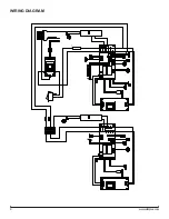
Страница 6: ...6 www dimplex com WIRING DIAGRAM FUSE...

Страница 7: ...er from the instructions above Figure 4 TERMINAL BLOCK REPLACEMENT Tools Required Phillips head screwdriver WARNING Disconnect power before attempting any maintenance to reduce the risk of electric sh...

Страница 8: ...cs assembly CAUTION Ensure that the switchboard and terminal block have not moved from their original locations and all wires are contained under the cover before reassembly 9 Re assemble the remainde...

Страница 9: ...s and reinsert the electronics assembly CAUTION Ensure that the switchboard and terminal block have not moved from their original locations and all wires are contained under the cover before reassembl...

Страница 10: ...bly CAUTION Ensure that the switchboard and terminal block have not moved from their original locations and all wires are contained under the cover before reassembly 10 Re assemble the remainder of th...

Страница 11: ...ronics assembly CAUTION Ensure that the switchboard and terminal block have not moved from their original locations and all wires are contained under the cover before reassembly 11 Re assemble the rem...

Страница 12: ...o prevent strain on the connector wire attached to it 4 Remove the cable clamp to allow for the assembly to be lifted out to better access the components 5 Holding the assembly at either end of the LE...

Страница 13: ...ontrol Replace remote control The flame effect has too much smoke or is coming out too fast Flame effect control is set too high Adjust the flame height on both the secondary and or primary controls F...

Страница 14: ...water source Improper operation Mist will begin emitting out of the unit after 45 sec onds of operation Transducer is not installed correctly Ensure that the connection has clicked into place Cord is...

Страница 15: ...the toggle switch in the On position and everything else Off 2 Press the troubleshooting button Figure 1D on the side that the testing is required unit will beep 3 Press the following buttons to test...

Отзывы: