


5
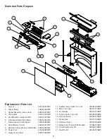
Maintenance
WARNINg:
Disconnect power before attempting any
maintenance or cleaning to reduce the risk of fire, electric
shock or damage to persons.
Light Bulb Replacement
Allow at least five (5) minutes for the light bulbs to cool
before touching them to avoid accidental burning of the skin.
The light bulbs need to be replaced when you notice a dark
section of the flame or when the clarity and detail of the log
Ember Bed exterior reduces. There are three (3) bulbs under
the Log Set, which generate the flames and embers, and two
(2) bulbs above the log that illuminate the log exterior.
Lower Light Bulb Requirements
Quantity of three (3) clear chandelier or candelabra bulbs
with an E-12 (small) socket base, 60 Watt rating. Example:
GE 60BC or Philips 60CTC.
Do not exceed 60 Watts per bulb.
Helpful Hints:
It is a good idea to replace all light bulbs at
one time if they are close to the end of their rated life. Group
replacement will reduce the number of times you need to
open the unit to replace light bulbs.
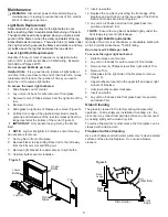
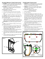
To access the lower light bulb area:
Slide fireplace out of mantel.
1.
Lay unit on it’s back for safe removal of front glass.
2.
Remove four (4) Phillips screws from the right side of the
3.
trim.
Remove the trim.
4.
Slide glass to right side of fireplace to remove (Figure 5).
5.
Pull the front edge of the plastic Ember Bed or plastic
6.
grate up and forward until the rear tab releases from the
ledge located at the bottom of the mirror (Figure 6).
!
IMPORTANT:
Only handle the Log Set by the Ember
Bed.
!
NOTE:
Log Set fits tightly into firebox, some force may
be necessary to remove.
Set Log Set in front of fireplace.
7.
Remove flicker rod by sliding flicker rod to the left away
8.
from the flicker motor and lifting out.
Remove light bracket for easier access to light bulbs.
9.
Unscrew bulbs counter clockwise.
10.
Insert new bulbs.
11.
Replace the Log Set by inserting the front edge of the
12.
fireplace and push down on the rear edge of the Ember
Bed until it snaps into place (Figure 6).
Lay unit on it’s back and slide front glass back into
13.
position and attach
trim.
!
NOTE:
Ensure the Log Set is installed tightly under the
back ledge to prevent light leakage.
Upper Light Bulb Requirements
Quantity of two (2) clear chandelier or candelabra bulbs with
an E-12 (small) socket base, 15 Watt rating.
Do not exceed 25 Watts per bulb.
To access the upper light bulb area:
Slide fireplace out of mantel.
1.
Lay unit on it’s back for safe removal of Front Glass.
2.
Remove four (4) Phillips screws from right side of Trim.
3.
Remove Trim.
4.
Slide glass to the right side of the fireplace to remove
5.
(Figure 5).
Upper bulbs are located in the upper left and upper right
6.
corners of fireplace.
Unscrew bulbs counter clockwise.
7.
Insert new bulbs.
8.
Lay unit on it’s back slide front glass back into position
9.
and attach Trim.
glass Cleaning
The glass is cleaned in the factory during the assembly
operation. During shipment, installation, handling, etc., the
clear door may collect dust particles, these can be removed
by dusting lightly with a clean dry cloth.
To remove fingerprints or other marks, the front glass can be
cleaned with a damp cloth.
Fireplace Surface Cleaning
Use a cloth dampened with warm water only to clean painted
surfaces of the electric fireplace. Do not use abrasive
cleaners.
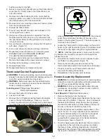
Lower
Bulbs
Upper
Bulbs
Trim
Front
Glass
Log Set
Figure 5
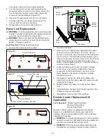
Back
Ledge
Log
Ember Bed
Rear
Tab
Front
Edge
Side Section
Figure 6