


3
•
Pressing the switch for a third time (“–” position)
the flame effect remains on, the heater is set to the
high heat setting, and all three red indicators flash
momentarily
• Pressing the switch down (“═” position) turns the unit
off
F. HEATER THERMOSTAT CONTROL
To adjust the temperature to your individual requirements,
turn the thermostat control clockwise all the way to turn
on the heater. When the room reached the desired
temperature, turn the thermostat knob counter clockwise
until you hear a click. Leave in this position to maintain the
room temperature at this setting. For additional heat, turn
clockwise until you hear the click again and the heater will
turn on.
!
NOTE:
The heater may emit a slight, harmless odor
when first used. This odor is a normal condition caused
by initial heating of internal heater parts and will not occur
again.
Resetting the Temperature Cutoff Switch
Should the heater overheat, an automatic cut out will turn
the fireplace off and it will not come back on without being
reset. It can be reset by switching the On/Off Switch to Off
and waiting five (5) minutes before switching the unit back
on.
!
NOTE:
If operating the unit with a remote control, the
remote may require re-initializing after turning the power
off.
CAUTION:
If you need to continuously reset the heater,
disconnect power and call Dimplex customer service at
1-888-DIMPLEX (1-888-346-7539).
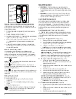
Remote Control
The fireplace is supplied with a radio frequency remote
control. This remote control has a range of approximately
50 feet (15.25 m), it does not have to be pointed at the
fireplace and can pass through most obstacles (including
walls). It is supplied with one of hundreds of independent
frequencies to prevent interference with other units.
!
NOTE:
Before attempting any operation with the
remote control, pull the plastic insulator strip out from
between the remote casing and battery cover (Figure 2).
!
NOTE:
The remote control is an EEPROM system;
therefore if power is interrupted for whatever reason,
the built-in receiver board will hold the memory of
the remote’s radio frequency for up to 24 hours. The
remote should continue to operate the fireplace as
normal once unit is re-powered. Re-initialization of the
remote control to the fireplace should only be required
if there is a loss of power to the receiver for longer than
24 hours. (i.e. power failure, main power switch is turned
off).
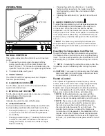
OPERATION
MANUAL CONTROLS
This section will explain the function of each convenient
control.
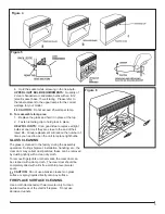
1. To access the controls, open the upper grille by
pulling, near the top right hand side, forward and
down. (Figure 1). To conceal the controls during the
operation, return the grille to its original upright position.
2.
To locate controls see Figure 2.
A. ON/OFF SWITCH
The ON/OFF SWITCH supplies power to all fireplace
functions (Heater/Flame).
B. FLAME SPEED CONTROL
Turn the flame speed control knob to adjust the flame
speed to the desired level.
C. INTERIOR LIGHT CONTROL
Turn the interior light control knob to increase or decrease
the brightness of the interior light.
D. LED INDICATORS
Indicates the current function of the fireplace
E. 3-POSITION SWITCH
To choose between flame effect setting, flame effect with
low heat setting, and flame effect with high heat setting.
• Pressing the switch up (“–” position) the flame effect
is turned on and the first red indicator light flashes
momentarily
• Pressing the switch again (“–” position) the flame effect
remains on, the heater is activated to the low heat
setting, and the first and second red indicator lights
flash momentarily
Figure 1
A
B
C
E
F
D
Figure 2
Содержание 6901170859
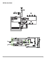
Страница 7: ...7 WIRING DIAGRAM Receiver Board...