


10
3. Pull the rear edge of the log set forward by grasping the
ember bed by the sides (handle the log set only by the
ember bed and not the logs) and pulling firmly until the
rear tab pops out from under the back ledge, then lift out.
4. Locate the cover plate by the switches and remove the
mounting screws.
5. Remove the cover plate.
6. Reach hand into the opening and locate the wiring for the
red heat indicator lights.
7. Pull the red heat indicator lights out through the bottom
of the mounting plate noting their original locations.
8. Reach hand into the opening and locate the heater se-
lection switch.
9. Depress the retainer clips on the rear of the switch and
push the switch up to release it from the mounting plate.
10. Disconnect the wiring connections noting their original
locations.
11. Remove the retaining screws on the light assembly
retaining plate and remove being careful not to damage
any of the wiring.
12. Reach hand into the opening created by removing the
light assembly. Locate the remote control receiver mount-
ed to the back of the unit and remove the wiring connec-
tions noting their original locations.
13. Depress the ends of the four plastic mounting posts with
pliers.
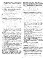
14. Properly orient the replacement circuit board and con-
nect all of the wiring connections in their original loca-
tions. See Figure 3 for new connections, if newer board
is received.
15. Reassemble in the reverse order as above.
NOTE: When installing the replacement circuit board ensure
the red heat indicator lights are installed into their original
mounting locations.
NOTE: To replace the log set, insert the front edge of the log
set and pushing back down until the rear tab snaps under
the back ledge and the logs are resting against the partially
reflective glass.
Input Voltage Changing
Tools Required:
Philips head screwdriver
Flat head screwdriver
WARNING:
If the fireplace was operating prior to servic
-
ing, allow at least 10 minutes for light bulbs and heating ele-
ments to cool off to avoid accidental burning of skin.
WARNING:
Disconnect power before attempting any
maintenance to reduce the risk of electric shock or damage
to persons.
The electric fireplace can be configured to operate on 120,
208 or 240 volt electrical service. The fireplace has been
configured from the factory to be installed on 208/240 volt
electrical service.
RECOMMENDED POWER SUPPLY WIRE SPECIFICATIONS
For 120 volt installations a two conductor, non-metallic
sheath cable with ground wire is recommended for the in-
coming power supply on fireplace inserts. Use the appropri
-
From Flicker Motor
Figure 3
Remote Control Receiver 3000200800
L
N
N
RL3 RL2
120VAC RL1
1
2
3
4
5
2
From Blower
From Heater
From Lights &
Flicker motor
From Lights
Line In
From Blower and Heater
Remote Control Receiver 3000430800RP
RL1
RL2
RL3
N
N
L
1
2
3
4
From Flicker Motor
From Lights
2
From Flicker Motor
From Lights
Switch
3
5
AC1
From Blower
From Heater
Line In
From Blower and Heater
From Blower and Heater
From Flicker Motor
and Lights
From Flicker Motor and Lights
From Blower and Heater
T11
T10
T9
T8 T9
T4
1
2
4
From Flicker Motor and Lights
Switch
3
5
From Heater
Line In
From Blower and Heater
From Flicker Motor
and Lights
From Blower and Heater
Remote Control Receiver 3000820500RP