www.digital-reference.com
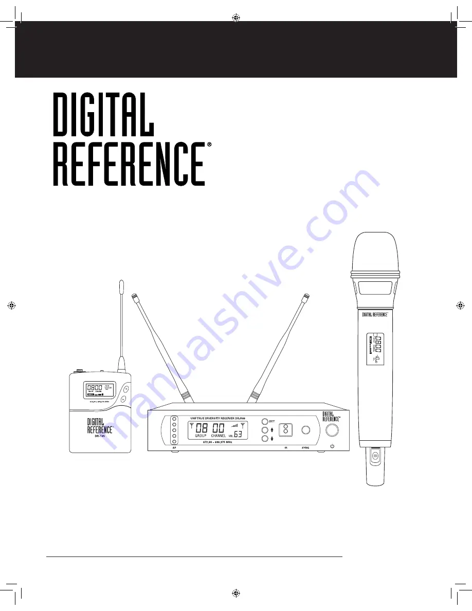
DR-4000 Series Professional UHF Wireless Systems
DR-4600 Handheld Dynamic Microphone SystemDR-4500 Instrument Body Pack System
8868 Digital Ref 4600 Manual.indd 1
10/27/09 10:37:10 AM
Страница 1: ...igital reference com DR 4000 Series Professional UHF Wireless Systems DR 4600 Handheld Dynamic Microphone System DR 4500 Instrument Body Pack System 8868 Digital Ref 4600 Manual indd 1 10 27 09 10 37...
Страница 2: ...be taken so that objects do not fall and liquids are not spilled into the unit through the ventilation ports or any other openings 13 CAUTION Electrical shock can result from removal of the receiver...
Страница 3: ...on 10 IR Sync 10 Adjusting the Audio Output 11 Adjusting the Squelch 11 TRANSMITTER OPERATION 12 Handheld 12 Body Pack 12 Batteries 13 Powering On Off 14 Instrument Use 14 DR T40 DR T45 Transmitter Me...
Страница 4: ...o included for these systems DR 4000 Series Systems DR 4600 Handheld Dynamic Microphone System DR 4500 Instrument Body Pack System DR 4000 Series UHF Wireless SystemS Features State of the art PLL UHF...
Страница 5: ...l housing with optional DR40RM1 single or DR40RM2 dual side by side rack mount kits All metal transmitter construction for both Handheld and Body Pack Selectable RF power output NOTE DR T40 and DR T45...
Страница 6: ...the receiver front panel The blue LCD screen will power on Finding a Clear Frequency The default setting for DR4600 Handheld is Group 8 Channel 00 DR4500 Instrument system is Group 3 Channel 00 Examin...
Страница 7: ...for a few seconds Locate the IR window on the back of the DR T40 transmitter and hold it 4 in front of the IR window of the Receiver Press the Sync button on the Receiver and wait 4 seconds The LCD w...
Страница 8: ...ceiver Press the Sync button on the Receiver and wait 4 seconds The LCD window on the transmitter will briefly turn blue and indicate the same Group Channel as the Receiver The Receiver s LCD will sho...
Страница 9: ...LCD Window 8 Diversity Receiver A B Indicator 9 RF Signal Meter 10 Frequency GROUP 11 Frequency CHANNEL 12 Output VOLUME Level Back 13 DC Power Input Jack 14 Balanced XLR Microphone Level Output 15 S...
Страница 10: ...device such as an effect processor or CD player Digital emissions can reduce RF range Installing Antennas Connect the two antennas included with your system to the two RF Connectors located on the ba...
Страница 11: ...t on press the Power Switch for 2 seconds The LCD will light and show the GROUP CHANNEL assignment RF Level Meter Diversity and Output Volume The 5 segment AF LED TREE will display the received audio...
Страница 12: ...se the UP DOWN buttons to change the value Press the SET button again to select CHANNEL and use the UP DOWN buttons to change the value See the RF Interference and Finding Open Channels section Page 1...
Страница 13: ...controls both the A and B True Diversity receiver sections The control should be adjusted counterclockwise to the minimum RF squelch setting at which the RF Level Meter and the Diversity Indicator wi...
Страница 14: ...y Meter 5 Segment 14 Input Volume Level Body Pack 1 3 5mm Locking Input Jack 2 ON MUTE OFF Switch 3 Antenna 4 LCD Display 5 IR Sync Receiver 6 RF Transmit Power 7 UP DOWN Buttons 8 SET Button 9 Batter...
Страница 15: ...d DR T45 Body Pack Transmitter Open the battery compartment cover by gently pressing the two latches centered on the side of the unit and gently pull the latching door open Insert the batteries noting...
Страница 16: ...ion No LCD or backlight is lit and the unit will turn off NOTE The RF Level Meter LCD RF and the Diversity A B Indicator LCD D on the receiver s LCD display should be on during normal operation Instru...
Страница 17: ...g the Transmitter to the Selected Channel The Transmitter must be set to the same GROUP CHANNEL setting as the corresponding receiver The Transmitter can be programmed manually using the SET or UP DOW...
Страница 18: ...r bars and an antenna icon If Sync fails use the transmitter s SET and UP DOWN buttons to match the Transmitter GROUP CHANNEL to the Receiver GROUP CHANNEL Turn the Power switch to On The wireless sys...
Страница 19: ...eater transmission distance but reduces the number of simultaneous systems on air and can overload the receiver at close distances Only use High Power mode if greater distance is required over the Low...
Страница 20: ...ent 1 Good Mic Placement The microphone is not in the direct path of the loudspeaker and the stage monitor is pointed at the null point of the cardioid microphone pattern 2 Poor Mic Placement The micr...
Страница 21: ...ding the selected CHANNEL i e the three channels above and below the selected CHANNEL If operating multiple DR 4000 Series systems simultaneously repeat this procedure with every new CHANNEL selected...
Страница 22: ...but never closer than 3 1 meter as that may overload the receiver s input circuitry and cause noise It is generally recommended that batteries should be removed anytime the transmitters are not being...
Страница 23: ...4 800 13 672 325 674 825 677 325 679 825 682 325 684 825 687 325 689 825 692 325 694 825 14 672 350 674 850 677 350 679 850 682 350 684 850 687 350 689 850 692 350 694 850 15 672 375 674 875 677 375 6...
Страница 24: ...95 575 44 673 100 675 600 678 100 680 600 683 100 685 600 688 100 690 600 693 100 695 600 45 673 125 675 625 678 125 680 625 683 125 685 625 688 125 690 625 693 125 695 625 46 673 150 675 650 678 150...
Страница 25: ...6 450 678 950 681 450 683 950 686 450 688 950 691 450 693 950 696 450 79 673 975 676 475 678 975 681 475 683 975 686 475 688 975 691 475 693 975 696 475 80 674 000 676 500 679 000 681 500 684 000 686...
Страница 26: ...RF levels A B diversity unbalanced receiver out Volume levels LED Display 5 segment LED tree indicating received audio levels from transmitter Audio Output Level Unbalanced output 360mV adjustable Bal...
Страница 27: ...pecific legal rights You may have other legal rights which vary from state to state Some states do not allow limitations on how long an implied warranty lasts so the above limitation may not apply to...
Страница 28: ...www digital reference com 0906 8868 8868 Digital Ref 4600 Manual indd 26 10 27 09 10 37 19 AM...