Digital Equipment VT 240 series Скачать руководство пользователя страница 1

Содержание VT 240 series

Страница 1: ...VT 240series Owner s Manual...

Страница 2: ...EK VT240 UG 003 VT 240series Owner s Manual Digital Equipment Corporation...

Страница 3: ...articular installation If this equipment does cause interference to radio or television reception which can be determined by turning the equipment off and on the user is encouraged to try to correct t...

Страница 4: ...System Box 2 Keyboard 2 How the VT240 Works 2 Operating States 3 Set Up 3 On Line 3 Local 3 Operating Modes 4 VT200 Mode 7 Bit Controls 4 VT200 Mode a Bit Controls 4 VT100 Mode 4 VT52 Mode 4 4010 4014...

Страница 5: ...racter 17 Editing Keypad 17 Auxiliary Keypad 17 Top Row Function Keys 18 Hold Screen 18 Print Screen 19 Set Up 19 Data Talk 19 Break 19 F11 ESC 20 F12 BS 20 F13 LF 20 Function Key Summary 20 Visual In...

Страница 6: ...31 Using a Three Stroke Compose Sequence 32 Using a Two Stroke Compose Sequence 33 Aborting or Restarting a Compose Sequence 33 CHAPTER 4 TERMINAL SET UP General 45 Using Set Up 46 Set Up Screens 46...

Страница 7: ...l Characters 107 Connect Disconnect 108 Printer Port Operation 109 Terminal Printer Data Flow 112 CHAPTER 6 PROBLEM SOLVING General 113 Common Operating Problems 113 Power Up Self Test 115 Performing...

Страница 8: ...4 6 Communications Set Up Screen 69 4 7 Printer Set Up Screen 75 4 8 Keyboard Set Up Screen 80 4 9 Tab Set Up Screen 85 4 10 Graphics Set Up Screen 87 4 11 4010 4014 Set Up Screen 90 4 12 Telephone S...

Страница 9: ...pose Sequences Multinational Mode 34 Valid Compose Sequences National Mode 39 Status Line Messages 49 Set Up Controls and Cursor Functions 50 Set Up Screens Summary 52 Set Up Directory Screen 55 Displ...

Страница 10: ...ators and connectors and shows their locations Chapter 3 Operating Procedures provides information on specific ter minal functions and operating procedures Chapter 4 Terminal Set Up describes each set...

Страница 11: ...s terminal specifications Appendix B Options Documentation and Supplies describes the options related documentation and supplies mentioned in this manual and how to order them Appendix C Keyboards sho...

Страница 12: ...ew of what these terminals are and what they do then briefly describes how the terminals work VT240 COMPONENTS The three main components of the VT240 series terminals are the monitor the system box an...

Страница 13: ...pewriter keyboard A single coiled cable connects the keyboard to the terminal There are 15 basic keyboards available with the VT240 See Appendix C Each keyboard is for a different language HOW THE VT2...

Страница 14: ...rminal communicate with a host computer Data entered at the keyboard is sent to the host computer Data received from the host computer is displayed on the monitor You can also display data entered fro...

Страница 15: ...selected in set up Chapter 4 NOTE In general most VT100 application programs will run in VT200 mode 7 bit controls VT200 Mode 8 Bit Controls This mode also executes standard ANSI functions and lets yo...

Страница 16: ...s from the keyboard or from the host computer You can use ReGIS graphics mode with application programs designed for Digital s VT125 terminals CRT SAVER FEATURE If during normal operation the terminal...

Страница 17: ......

Страница 18: ...rmation about the terminal s controls indicators and connectors The chapter also describes the keyboard including the three keypads and special function keys SYSTEM BOX The system box controls indicat...

Страница 19: ...NITOR CONNECTOR POWER CORD CONNECTOR DO NOT REMOVE LABEL YETI I 7FUSE Comm EIA HOST PORT CONNECTOR Figure 2 1 COMPOSITE VIDEO OUTPUT CONNECTOR t VOLTAGE SELECTION KB KEYBOARD CONNECTOR PR PRINTER PORT...

Страница 20: ...CONTROLS INDICATORS AND CONNECTORS 9...

Страница 21: ...s and connectors are shown in Figure 2 2 and described in Table 2 2 SCREEN r J I E OlD 1111II11111111111111illl PUSHBUTTON POST VIDEO MONITOR CONNECTOR F nnnnnn i nn BRIGHTNESS KEYBOARD CONTROL CONNEC...

Страница 22: ...CONTROLS INDICATORS AND CONNECTORS 11...

Страница 23: ...nnectors are shown in Figure 2 3 and described in Table 2 3 POWER SWITCH FUSE ACINPUT CONNECTOR CABLE CONNECTORS 6 MONITOR POWER OK INDICATOR CONTRAST BRIGHTNESS DB SYNC SWITCH 19 I SYNC o r CONNECTOR...

Страница 24: ...CONTROLS INDICATORS AND CONNECTORS 13...

Страница 25: ...nt screen location that the terminal is referencing This location is the point on the screen most recently moved to or drawn to You can turn the graphics cursor on or off in set up KEYBOARD The keyboa...

Страница 26: ...ng the Tab key sends a horizontal tab which normally moves the cursor to the next tab stop LJ Ctrl Holding down the Ctrl key and pressing another key sends a control code to the system A control code...

Страница 27: ...n this manual keyboard control functions using Shift appear as follows Shift other key For example Shift Print Screen means to press and hold Shift while pressing the Print Screen key oReturn Pressing...

Страница 28: ...e six editing keys have functions corresponding to their legends See your application software manual for specific information AUXILIARY KEYPAD The auxiliary keypad Figure 2 7 lets you enter numeric d...

Страница 29: ...on keys Figure 2 8 have functions assigned by the application software Your application software manual should describe the function of these keys The following paragraphs describe the predefined top...

Страница 30: ...o enter or exit the set up state See Chapter 4 Data Talk D Data Talk The Data Talk key only operates if the optional integral modem is installed See Chapter 3 Break D Break T le Break key works alone...

Страница 31: ...lly a function key used by application prc grams In VT100 and VT52 modes it sends an LF line feed character Function Key Summary The following keys are function keys used by application programs Each...

Страница 32: ...frozen See the Hold Screen key description Lock Indicator The Lock indicator comes on to indicate that the keyboard will send uppercase characters only See the Lock key description Compose Indicator...

Страница 33: ...g exceptions You press Shift or Ctrl These keys do not make a keyclick because they do not send a character They modify characters sent by other keys The Wait indicator is on characters from the keybo...

Страница 34: ...terminal func tions and operating procedures However your main reference source is the documentation for your application software PRINTING The VT240 has a built in serial printer interface that suppo...

Страница 35: ...hen the terminal 1 receives a line feed form feed or vertical tab or 2 automatically wraps the line When selected Au to Pr i nt Mode appears on the status line in set up You can use all keyboard print...

Страница 36: ...UTO DIALER OPTION The integral modem auto dialer option lets you use a telephone for normal voice communication and the terminal for data communication on the same communications line This option also...

Страница 37: ...MODE FEATURES The following sections explain how to use dialer mode features such as dialing and redialing telephone numbers and dialing stored telephone numbers Typing a Telephone Number at the Keyb...

Страница 38: ...er Waiting for connection The terminal remembers this number until you dial another Redialing the Last Telephone Number Dialed You can redial the last telephone number you dialed at any time without e...

Страница 39: ...hone numbers in set up You can then dial these stored numbers designated A and B in dialer mode by pressing the A or B key followed by Return The terminal automatically dials the telephone numbers NOT...

Страница 40: ...e monitor displays the following message Di a 11 ng number Waiting for connection NOTE The monitor screen does not display characters if you chose to con ceal the number See the Te ephone Set Up Scree...

Страница 41: ...30 OPERATING PROCEDURES...

Страница 42: ...r key then you press two keys whose characters form a valid compose sequence You can use two stroke sequences on all keyboards except the North Ameri can keyboard Two stroke sequences are faster than...

Страница 43: ...s listed in column 1 in one or more ways With a standard key if available on that keyboard With a three stroke compose sequence always With a two stroke compose sequence if the diacritical mark is ava...

Страница 44: ...terminal is in compose mode 3 Type the second character shown in column 3 For example to create e with a grave accent on a Danish keyboard press the key that has the grave accent and then type e When...

Страница 45: ...34 OPERATING PROCEDURES...

Страница 46: ......

Страница 47: ...36 OPERATING PROCEDURES...

Страница 48: ...OPERATING PROCEDURES 37...

Страница 49: ...38 OPERATING PROCEDURES...

Страница 50: ...OPERATING PROCEDURES 39...

Страница 51: ...40 OPERATING PROCEDURES...

Страница 52: ...OPERATING PROCEDURES 41...

Страница 53: ...42 OPERATING PROCEDURES...

Страница 54: ...OPERATING PROCEDURES 43...

Страница 55: ...44 OPERATING PROCEDURES...

Страница 56: ...ures in an NVR nonvolatile RAM memory NVR memory retains theses features even when power is shut off In addition to storing operator selected features the terminal also retains the factory default set...

Страница 57: ...can only display one set up screen at a time You can enter the Set Up Directory screen from any other set up screen SET UP SCREENS Each set up screen occupies the bottom third of the monitor screen C...

Страница 58: ...Application Cursor Keys I R Mod Pc No Pc Figure 4 2 Screen Title Sample Set Up Screen STATUS LINE The screen title identifies the current set up screen There are 10 set up screens nine standard one o...

Страница 59: ...elect an action field and press the Enter key the terminal performs the action For example each scr en has an action field that reads To Directory When you select this field and press Enter the Set Up...

Страница 60: ...TERMINAL SET UP 49...

Страница 61: ...l the entry without changing the original value press an arrow key to change the field selection See the following Set Up Controls and Cursor section Set Up Controls and Cursor The VT240 uses a field...

Страница 62: ...the Enter key The terminal replaces the Set Up Directory screen with the Display Set Up screen Figure 4 4 4 Use the arrow keys to move the field cursor to the 80 Columns field 5 Press Enter The field...

Страница 63: ...creens and their features When you select the various set up features you want to use make sure to check off the box beside the parameter value selected for that feature This gives you a record of the...

Страница 64: ...TERMINAL SET UP 53...

Страница 65: ...set up screen The Set Up Directory screen also contains fields you can use to select terminal operating features Table 4 4 describes all fields on this screen Set Up Directory VT240 V2 0 I M 4 1 1 10...

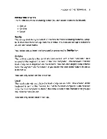
Страница 66: ...TERMINAL SET Up 55...

Страница 67: ...56 TERMINAL SET UP...

Страница 68: ...TERMINAL SET UP 57...

Страница 69: ...58 TERMINAL SET UP...

Страница 70: ...TERMINAL SET UP 59...

Страница 71: ...e monitor display characteristics Table 4 5 describes all fields on this screen Display Set Up VT240V2 0 To Next Set Up 4 1 1_ 1 11 Interpret Controls H tilii iifl jj Light Text Dark Screen Monochrome...

Страница 72: ...TERMINAL SET UP 61...

Страница 73: ...62 TERMINAL SET UP...

Страница 74: ...TERMINAL SET UP 63...

Страница 75: ...used general operating features Table 4 6 describes all fields on this screen General Set Up 4 111 1 4 4 14 VT200 Mode 7 Bit Controls User Defined Keys Unlocked User Features Unlocked VT240 V2 0 IVT24...

Страница 76: ...TERMINAL SET UP 65...

Страница 77: ...66 TERMINAL SET UP...

Страница 78: ...TERMINAL SET UP 67...

Страница 79: ...68 TERMINAL SET UP...

Страница 80: ...environment between the terminal and host Table 4 7 describes all fields on this screen Communications Set Up VT240 V2 0 O ii lI Recelve Transmit feliM 1 8 BIts No Parity UMml IIS I EIA Port Data Lead...

Страница 81: ...70 TERMINAL SET UP...

Страница 82: ...TERMINAL SET UP 71...

Страница 83: ...72 TERMINAL SET UP...

Страница 84: ...TERMINAL SET UP 73...

Страница 85: ...74 TERMINAL SET UP...

Страница 86: ...xiliary device operations with the VT240 Table 4 8 describes all fields on this screen Printer Set Up VT240 V2 0 To Next Set Up No Pr Itller to Host Normal Pr lilt Mode H M Print Full Page Print Nelll...

Страница 87: ...76 TERMINAL SET UP...

Страница 88: ...TERMINAL SET UP 77...

Страница 89: ...78 TERMINAL SET UP...

Страница 90: ...TERMINAL SET UP 79...

Страница 91: ...features Table 4 9 describes all fields on this screen Keyboard Set Up VT240 V2 0 To Next Set Up Mii h Typewrltel Keys Auto Repeat Marqln Bell No Auto Answerback Answerback VT240 Answerback Message f...

Страница 92: ...TERMINAL SET UP 81...

Страница 93: ...82 TERMINAL SET UP...

Страница 94: ...TERMINAL SET UP 83...

Страница 95: ...84 TERMINAL SET UP...

Страница 96: ...n be either 80 or 132 columns wide depending on the number of columns set See Co 1urnn 5 in the Display Set Up screen There are two possible settings for each tab stop field the letter T tab stop sett...

Страница 97: ...86 TERMINAL SET UP...

Страница 98: ...4 11 describes all fields on this screen NOTE To set Tektronix 4010 4014 characteristics see your application software manuals Graphics Set Up VT240 V2 0 To Next Set Up To 4010 4014 Set Up Graphics C...

Страница 99: ...88 TERMINAL SET UP...

Страница 100: ...TERMINAL SET UP 89...

Страница 101: ...ics characteristics Table 4 12 describes all fields on this screen NOTE To set Tektronix 4010 4014 characteristics see your application software manuals 4010 4014 Set Up VT240 V2 0 pe II lIIgal l Alig...

Страница 102: ...TERMINAL SET UP 91...

Страница 103: ...92 TERMINAL SET UP...

Страница 104: ...describes all fields on this screen NOTE You can only select the Telephone Set Up screen if the VT24X AA integral modem option is installed Telephone Set Up VT240 V2 0 p PNi 61 16 I r II plllJlII 111...

Страница 105: ...94 TERMINAL SET UP...

Страница 106: ...TERMINAL SET UP 95...

Страница 107: ......

Страница 108: ...nal Communications Set Up screen and the printer Printer Set Up screen The VT240 operates in accordance with the following national and international communications standards EIA Standard RS232C RS423...

Страница 109: ...ocal printer Tables 5 1 through 5 3 describe the interface signals for the three connectors NOTE Only the connector pins listed in Tables 5 1 through 5 3 are used MODEMS The VT240 can operate with all...

Страница 110: ...COMMUNICATION 99...

Страница 111: ...100 COMMUNICATION...

Страница 112: ...COMMUNICATION 101...

Страница 113: ...102 COMMUNICATION...

Страница 114: ...M CABLE BCC04 10 10 feet 25 25 feet 50 50 feet 9 PIN PRINTER PORT Cables MODEM PRINTER CABLE BCC05 10 10 feet 25 25 feet 50 50 feet 50 50 feet HOST COMPUTER HOST COMPUTER HOST COMPUTER HOST COMPUTER P...

Страница 115: ...ters When the input buffer fills to 64 256 512 or 1024 characters selected from the Communications Set Up screen the terminal sends an XOFF character if you enabled XOFF from the Communications Set Up...

Страница 116: ...er sent was XOFF A clear terminal operation is performed A recall operation is performed The power up self test is completed Chapter 6 You press the Hold Screen key to release the screen when the inpu...

Страница 117: ...mulas to determine how fast the host computer must respond to the first XOFF character to prevent loss of characters due to buffer overflow Calculate the overflow first then host response time NOTE Th...

Страница 118: ...buffer has 1024 characters in it OVFL 2048 1024 3 x 4800 4800 1021 characters HRST 1021 x 8 bits 1 bit 0 bits 1 4800 2 13 seconds Therefore the host computer must stop sending data in 2 13 seconds or...

Страница 119: ...owing conditions cause communications line disconnect Typing Shift Break Invoking Recall or Defaul t values in the Set Up Directory screen Loss of DSR Loss of RLSD for a time you defined in set up No...

Страница 120: ...nput device printer to host mode you can send data from the printer or auxiliary device and the keyboard to the host Figure 5 3 The terminal treats data from the printer port the same as keyboard data...

Страница 121: ...ut device printer controller mode the device connected to the printer port is treated as a terminal while the VT240 monitors line traffic Figure 5 5 All characters from the host are sent directly to t...

Страница 122: ...I L____ _ Figure 5 4 PRINTER Printer Port as Output Device Normal Print Mode rvrno 1 1 SYSTEM 1 _1__ I KrnoARD BOX L____ _ Figure 5 5 PRINTER Printer Port as Input Output Device Printer Controller Mod...

Страница 123: ...through the printer port The terminal starts send ing data again when it receives XON or when a clear comm operation is performed The terminal has a 256 character input buffer for the printer port wit...

Страница 124: ...if you have a problem with the VT240 The chapter provides a problem checklist and describes the power up self test COMMON OPERATING PROBLEMS Table 6 1 lists common operating problems and their possib...

Страница 125: ...114 PROBLEM SOLVI NG...

Страница 126: ...al The terminal cannot respond to commands other than those used for the test itself When the test cycle ends control returns to the terminal In the self test mode the monitor screen and the keyboard...

Страница 127: ...ul power up self test ends with all keyboard indicators off the power ok indicator on and the screen displaying the message shown in Figure 6 1 The message is erased when a character is received from...

Страница 128: ...PROBLEM SOLVING 117...

Страница 129: ...d Service number for assistance Before calling make sure to note the exact nature of the problem when it occurred and any error messages or codes that appeared Information about your warranty Digital...

Страница 130: ...box Height Width Depth Weight Keyboard Height Width Depth Weight Monochrome monitor Height Width Depth Weight Adjustable tilt 10 2 em 4 in 45 7 em 18 in 30 5 em 12 in 7 2 kg 16 Ibs 5 1 em 2 in 53 3 em...

Страница 131: ...titude Electrical Line voltage switch selectable Line frequency Power cord 32 4 cm 12 75 in 38 em 15 in 42 1 cm 17 in 16 6 kg 36 6 Ibs 10 to 40 C 50 to 104 F 10 to 90 28 C 82 F 2 C 36 F 2 4 km 8000 ft...

Страница 132: ...x 1 3 mm for 132 columns Active display size 20 2 cm x 11 5 cm 8 in x 5 in Character sets ASCII national replacement NRC DEC supplemental and DEC special graphics in loadable 80 or 132 column font Con...

Страница 133: ...essing versions available in 15 languages Sculptured key array Matte texture finish keys Home row key height 30 mm 1 18 in above desktop 1 27 cm 0 5 in square 1 9 cm 0 75 in center to center single wi...

Страница 134: ...PTIONS There are two options available for the VT240 You can order these options from Digital Part Number VT24X AA VR24X AA Description Integral modem auto dialer This option is a circuit board instal...

Страница 135: ...g character codes and control sequences needed to generate terminal control programs This manual also provides an overview of ReGIS graphics and Tektronix 4010 4014 programming Describes the installat...

Страница 136: ...not provide part numbers for printed circuit board components Provides a detailed parts breakdown of the VT241 field replaceable units Does not provide part numbers for printed circuit board component...

Страница 137: ...by phone from 8 30 a m to 6 00 p m EST or by mail Continental USA and Puerto Rico Call 800 258 1710 or mail to Digital Equipment Corporation P O Box CS2008 Nashua NH 03061 New Hampshire Alaska Hawaii...

Страница 138: ...s standard and word processing The key positions on both types of keyboards are the same However the word processing version has different key legends appropriate to word processing only United States...

Страница 139: ...C 0 DDDI Ii O D D D D r DD Do 8 ill ill i u lliJ ill J 6 L jD 2 D D Q IIDD0 _10 t GJtj Q QD D 0 D a 8D O QDtJ fD co O J D Q tJ 15 tJbJtJ c III d u Q E lb J C l D s tJ b t Q 0 iD z J BDlJDil j 0 Q D D...

Страница 140: ...APPENDIX C 129...

Страница 141: ...130 APPENDIX C...

Страница 142: ...APPENDIX C 131...

Страница 143: ...132 APPENDIX C...

Страница 144: ...APPENDIX C 133...

Страница 145: ...134 APPENDIX C...

Страница 146: ...APPENDIX C 135...

Страница 147: ...136 APPENDIX C...

Страница 148: ...APPENDIX C 137...

Страница 149: ...138 APPENDIX C...

Страница 150: ...D DDDI II D D D D D It DD Do j 0 Iill I EJ J 0 OJ 0iJ s oS i g il 6 D 2 D N00 Ql i ii 1 O DDb _ITO J I 5 I D QtJbD D QtJ fO D Q l J e b tJD D h tb J 00 c u 0 0 Q tJ w a Q C 1 0 Q GJ C I D D JD l u Q...

Страница 151: ...140 APPENDIX C...

Страница 152: ...APPENDIX C 141...

Страница 153: ...D D J J D D LJ J D D DD o 10 j GIJ l illLEJ I IT IIill 16 GSD 2 D D D D UJ 6 j j 0 lIo D tJl J D QtJbJ D Qbb D N C J 2 Ie tJ ctI E tJo Q S2 tJ D 0 c D ctI QtJ J 1 Q N 1 D Q b w 00 en D d c J 11 J JOl...

Страница 154: ...4 Character set mode 67 Character sets DEC multinational 4 5 national 4 5 INDEX Clear comm 57 Clear display 56 Communications 97 112 buffer overflow 106 107 cables 103 character format 72 78 104 conn...

Страница 155: ...ault settings 59 Delete key 16 26 DEL Implies Lo Y feature 92 Dialer mode 26 30 call status 28 dialing a new telephone number 27 dialing a stored telephone number 28 disconnecting calls 29 redialing a...

Страница 156: ...tor 2 10 13 monochrome 10 11 color 12 13 Multinational mode 5 67 INDEX 145 N National mode 5 67 National replacement character sets 21 Next Screen key 21 0 On line 3 Operating modes 4010 4014 4 65 VT5...

Страница 157: ...creen summary Set up screens 46 52 95 4010 4014 90 92 Communications 69 74 Directory 54 59 Display 60 63 General 64 68 Graphics 87 89 Keyboard 80 84 Printer 75 79 Summary 52 53 Tab 85 86 Telephone 93...

Страница 158: ...w Wait indicator 21 Wrapping text 62 x XJ delete key 16 26 XOFF feature 46 71 77 INDEX 147...

Страница 159: ......

Страница 160: ...er If you perform your own maintenance you should use our fast turnaround module and subassembly repair service called DECmailer For more information on any of Digital s maintenance services call the...

Страница 161: ...Printed in U S A EK VT240 UG 003...

Страница 162: ...Printed in U S A EK VT240 UG 003...

Отзывы: