background image

Содержание VAXstation 2000

Страница 1: ...VAXstation 2000 Hardware Installation Guide Order Number EK VAXAC IN 003 Read this guide first to install and test the VAXstation 2000 hardware digital equipment corporation maynard massachusetts...

Страница 2: ...eststhe user s critical evaluationto assist in preparing future documentation The followingare trademarks of Digital Equipment Corporation DEBET MicroVAX UNIBUS DEC MicroVMS ULTRIX 32 DECconnect PDF U...

Страница 3: ...the VR290 Color Monitor 21 Connect the Pointing Device to the VR290 Color Monitor 23 VR260 Monochrome Monitor 25 Install Video Cable Assembly VR260 Monochrome Monitor 29 Connect the Keyboard to the VR...

Страница 4: ...62 Installing an Expansion Box 64 Positioning the Expansion Box 65 Connecting the Tape Drive Cable 67 Connecting the Disk Drive Cable 71 Connect the Power Cords 75 Power Up the Monitor 82 Set the bri...

Страница 5: ...Monitor Cable 16 15 Tilt lock Lever VR290 Color Monitor 18 16 R G and B Sockets VR290 Color Monitor 19 17 Video Cable Assembly Knob VR290 Color Monitor 20 18 Installing the Keyboard Feet VR290 Color M...

Страница 6: ...Device 44 43 Mounting Video CableAssembly on VR160 Monitor 45 44 Setting the VR150 on a Level Surface 46 45 Adjusting Tilt VR150 Monitor 47 46 Mounting Video Cable Assembly on VR150 Monitor 48 47 Con...

Страница 7: ...r 77 73 On Off Switch VR150 Monochrome Monitor 78 74 Power Cord Connection VR290 Color Monitor 79 75 Power Cord Connection VR260 Monochrome Monitor 79 76 Power Cord Connection VR160 Color Monitor 80 7...

Страница 8: ...ware and operating system software documentation in the following order 1 Hardware Installation Information a VAXstation 2000 Hardware Installation Guide b Workstations and MicroVAX 2000 Network Guide...

Страница 9: ...e steps above have been completed install the networking hardware and install the operating system software Special Notices The following notices appear throughout this guide Notes Contain general or...

Страница 10: ...tion 2000 Owner s Manual Space Planning Plan for 10 cm 4 in clearance on all sides of the VAXstation 2000 system unit and monitor to allow air circulation through the equipment Do not block the vents...

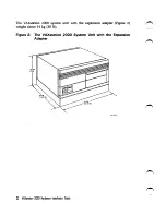
Страница 11: ...tation 2000 system unit with the expansion adapter Figure 2 weighs about 14 kg 30 lb Figure 2 The VAXstation 2000 System Unit with the Expansion Adapter 18CM 7INI 2 VAXstation 2000 Hardware Installati...

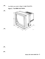
Страница 12: ...The VR290 color monitor in Figure 3 weighs 36 kg 80 lb Figure 3 The VR290 Color Monitor S4 6CM 21 S IN VAXstation 20Q0 Hardware Installation Guide 3...

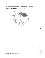
Страница 13: ...The VR260 monochrome monitor in Figure 4weighs 18 kg 40 lb Figure 4 The VR260 Monochrome Monitor 39 CM 15 4 IN 44 5 CM 17 5 IN 4 VAXstation 2000 Hardware Installation Guide 39 5 CM 15 6 IN...

Страница 14: ...The VR160 color monitor in Figure 5 weighs 23 kg 51 lb Figure 5 The VR160 Color Monitor 39 4 CM 15 5 IN M O 12S8 7 VAXstation 2000 Hardware Installation Guide 5...

Страница 15: ...The VR150 monochrome monitor in Figure 6 weighs 16 34 kg 36 lb Figure 6 The VR150 Monochrome Monitor 39 4 CM I15 SIN 36 9 CM 14 51 INI 6 VAXstation 2000 Hardware Installation Guide 40 3 CM 15 9 IN...

Страница 16: ...can interfere with system cooling and damage hardware diskettes andtape cartridges Store supplies such as diskettes and tape cartridges at the same temperature and humidity levels as recommended for t...

Страница 17: ...e received Keep the packing slip The serial number of the fixed disk is on the packing slip You will need this serial number to format the fixed disk Note K you have a diskless system you will receive...

Страница 18: ...ATOR 2 BOTTOM DRESS COVER MONOCHROME OR MONITOR BC18P VIDEO CABLE ASSEMBLY a a HARDWARE INFORMATION KIT VAXstation 2000 HARDWARE INSTALLA TION GUIDE THIS GUIDE VAXstation 2000 OWNER S MANUAL Workstati...

Страница 19: ...mentation Certain hardware options such as printers a tilt swivel base for the VR260 monochrome monitor order number VRIOX AA the tablet or expansion boxes are also packaged in separate boxes Other op...

Страница 20: ...m unit Figure 9 Cable restraining Bar CABLE RESTRAINING BAR VAXstation 2000 REARVIEW 1 You may set up the VAXstation 2000 system unit on its bottom rubber feet or on its side either side If you choose...

Страница 21: ...Cover on System Unit 2 m oooz uoirtKXVA BOTTOM DRESS COVER Place the VAXstation 2000 system unit in either of the recommended positions on a level surface All the illustrations in this guide show the...

Страница 22: ...the VAXstation 2000 system unit do not place the system unit on its front as it may damage the drive door Caution Never disconnect or connect the video cable to the system unit while the power is on...

Страница 23: ...ate video cable to the video port on the rear of the VAXstation 2000 system unit The video port is identified with the video icon 4 Insert the monitor video cable with the video icon side of the monit...

Страница 24: ...Figure 13 Connecting the Monitor Cable to the System Unit CABLE RESTRAINING BAR VIDEO ICON MONITOR CABLE VAXstation 2000 REARVIEW VAXstation 2000 Hardware Installation Guide 15...

Страница 25: ...thumbscrews on the monitor video cable by turning them clockwise with yourfingers Figure 14 Figure 14 Tiglitening the Thumbscrews on the Monitor Cable I MLO 1351 87 16 VAXstation 2000 Hardware Instal...

Страница 26: ...onitor Caution Because of the weight of the monitor you need two people to move the monitor 1 Locate the VR290 color monitor 2 Place the monitor on a level surface near the VAXstation 2000 system unit...

Страница 27: ...e 15 Tilt lock Lever VR290 Color Monitor TILT LOCK LEVER b Tilt the monitor to the desired position c Slide the lever toward you to lock the monitor in place 18 VAXstation 2000 Hardware Installation G...

Страница 28: ...90 color monitor The shorter knob is for the VR150 monochrome monitor with gray scale capabilities 1 Insert the connectors of the R G and B video cables into the corresponding R G and B sockets on the...

Страница 29: ...the knob Figure 17 on the video cable assembly clockwise to _ secure it to the monitor Figure 17 Video Cable Assembly Knob VR290 Color Monitor KNOB TO SYSTEM CABLE ASSEMBLY MOUNTING HOLE Note The vol...

Страница 30: ...feet Figure 18 Installation of the keyboard feet is optional Figure 18 Installing the Keyboard Feet VR290 Color Monitor KEYBOARD FEET KEYBOARD BOTTOM VIEW 3 Turn the keyboard right side up Caution Nev...

Страница 31: ...ows the keyboard connected to the VR290 color monitor The connection on the video cableassemblyis identified with a keyboard device icon Figure 19 Keyboard Connection VR290 Color Monitor KEYBOARD DEVI...

Страница 32: ...K 2 Ifyou are installing a tablet attach the puck orstylus to the tablet before connecting the tablet to the VAXstation 2000 Theinstructions that come with the tablet explain how to connect those comp...

Страница 33: ...21 The connection on the video cable assembly is labeledwith a pointing device icon Figure 21 Pointing Device Connection VR290 Color Monitor COLOR MONrrOR VIDEO CABLE ASSEMBLY POINTING DEVICE ICON TO...

Страница 34: ...t side up on a level surface near the VAXstation 2000 system unit and position the monitor for ease of use Ifyou have an optional tilt swivel base for the monitor do the following to set it up a Place...

Страница 35: ...260 Monochrome Monitor d Position the tilt swivel base over the monitor with the tilt lever on the front screen side of the monitor e Lower the base so that the four monitor feet go into the correspon...

Страница 36: ...se toward the back of the system until the base slides and locks in place Figure 24 Figure 24 Locking Tilt swivel Base in Place VR260 Monochrome Monitor TjlT LEVER I VAXstation 2000 Hardware Installat...

Страница 37: ...monitor for ease of use i To adjust the tilt of the monitor press the tilt lever down and move the monjitor to the desired angle The monitor locks into place when you take your hand off the tilt leve...

Страница 38: ...260 Monochrome Monitor with 4 plane Graphics Coprocessor to install the color video cable assembly on your monochrome monitor VR260 Monochrome Monitor Without 4 plane Graphics Coprocessor 1 Insert the...

Страница 39: ...the video connector on the rear of the monitor Turn the knob clockwise to screw in the video cable assembly Figure 27 Figure 27 Connecting Video Cable Assembly to VR260 Monochrome Monitor CABLE ASSEM...

Страница 40: ...on the back of the monitor Figure 28 2 Turn the connector clockwise to fasten Note The R and B connectors will hang freely do not connect them to anything Figure 28 Connecting G Cable Connector of th...

Страница 41: ...Insert the knob into the color video cable assembly 5 Turn the knob Figure 29 on the video cable assembly clockwise to secure it to the monitor Figure 29 Video Cable Assembly Knob CABLE ASSEMBLY MOUNT...

Страница 42: ...chrome Monitor KEYBOARD FEET KEYBOARD BOTTOM VIEW 3 Turn the keyboard right side up Caution Never disconnect or connect the keyboard cable while the system power is on 4 Connect the free end of the ke...

Страница 43: ...hrome Monitor KEYBOARD DEVICE ICON TO KEYBOARD 1 TO SYSTEM MONOCHROME MONITOR VIDEO CABLE ASSEMBLY Figure 32 Keyboard Connection VR260 Monochrome Monitor and Color Cable 34 VAXstation 2000 Hardware In...

Страница 44: ...rome Monitor MOUSE TABLET TABLET STYLUS rABLET PUCK 2 Ifyou are installing a tablet attach the puck orstylus to the tablet before connecting the tablet to the VAXstation 2000 The instructions that com...

Страница 45: ...into the appropriate video cable assembly Figure 34 or Figure 35 The connection on thevideo cable assembly islabeled with a pointing device icon Figure 34 Pointing Device Connection VR260 Monochrome M...

Страница 46: ...ointing Device Connection VR260 Monochrome Monitor with Color Cable TO KEYBOARD TO POINTINGDEVICE POINTING DEVICE ICON COLOR MONITOR VIDEO CABLE ASSEMBLY TO SYSTEM VAXstation 2000 Hardware Installatio...

Страница 47: ...igure 36 Caution An incorrect voltage select switch setting will damage the monitor Figure 36 Voltage Switch Setting for the VR260 Monochrome Monitor TO SYSTEM 38 VAXstation 2000 Hardware Installation...

Страница 48: ...a level surface near the VAXstation 2000 system unit Figure 37 Caution This procedure requires two people The monitor weighs 23 kilograms 51 pounds Figure 37 Setting the VR160 on a Level Surface VAXst...

Страница 49: ...l the monitor in a complete circle you may damage the base Toset the angle tilt the monitor forward or backward to the desired position You can swivel the monitor about its base and still maintain the...

Страница 50: ...he monitor Figure 39 in the following order Note Push each cable in and turn each connector clockwise until it clicks and locks in place a Connect the blue signal cable to the connector labeled B b Co...

Страница 51: ...installing a tablet attach the puck or stylus to the tablet before connecting the tablet to the VAXstation 2000 The instructions that come with the tablet explain how to connect those components Cauti...

Страница 52: ...olor Monitor KEYBOARD FEET KEYBOARD BOTTOM VIEW 3 Turn the keyboard right side up Caution Never disconnect or connect the pointing device cable while the system power is on 4 Connect the keyboard cabl...

Страница 53: ...Figure 42 Connecting the Keyboard Cable and Pointing Device 44 VAXstation 2000 Hardware Installation Guide KEYBOARD CABLE MOUSE CABLE...

Страница 54: ...unting plate when you start and finish securing the cable to the monitor Caution Failure to secure the video cable assembly screw to the cable mounting plate may strain the cable and may also cause ra...

Страница 55: ...el surface near the VAXstation 2000 system unit Figure 44 Caution This procedure requires two people The monitor weighs 16 34 kilograms 36 pounds Figure 44 Setting the VR150 on a Level Surface MLO 135...

Страница 56: ...l the monitor in a complete circle you may damage the base To set the angle tilt the monitor forward or backward to the desired position You can swivel the monitor about its base and still maintain th...

Страница 57: ...cable to use the 4 plane graphics coprocessor with your monochrome monitor VR150 Monochrome Monitor without Gray scale 1 Screw the video cable assembly intothe cable mounting plate Figure 46 Caution F...

Страница 58: ...2 Connect the video cable to the video connector on the rear panel 3 Push the cable in and turn the connector clockwise to lock it in place Figure 47 Figure 47 Connecting the Video Cable VR150 Monitor...

Страница 59: ...50 Monitor Color Cable AfmmwMmm VIDEO CABLE CABLE MOUNTING ASSEMBLY PLATE Caution Failure to secure the video cable assembly to the cable mounting plate may strain the cable and may also cause radio e...

Страница 60: ...Note The R and B connectors will hang freely do not connect them to anything Figure 49 Connecting G Cable Connector VR150 Monitor Amm m...

Страница 61: ...PUCK If you are installing a tablet attach the puck or stylus to the tablet before connecting the tablet to the VAXstation 2000 The instructions that come with the tablet explain how to connect those...

Страница 62: ...l Figure 51 Installing the Keyboard Feet VR150 Monochrome Monitor KEYBOARD FEET KEYBOARD BOTTOM VIEW 3 Turn the keyboard right side up Caution Never disconnect or connect the pointing device cable whi...

Страница 63: ...Figure 52 Pointing Device and Keyboard Connection VR150 Monitor Ammmmmm MOUSECABlE EYBOARDCABLE 54 VAXstation 2000 Hardware Installation Guide...

Страница 64: ...ce and Keyboard Connection VR150 Monitor with Color Cable Mouse CA8LE K6VBOARD CA8LE If you do not have any options to install proceed to the section on Connect the Power Cords VAXstation 2000 Hardwar...

Страница 65: ...er or plotter to the VAXstation 2000 You must order a cablein addition to the printer or plotter Mostprinters require the BCC05 cable however the LA75 printer requires the DECconnect office cable part...

Страница 66: ...5 or BCC24 05 Attach the larger end of the printer or plotter cable to the back of the printer or plotter Check the documentation that shipped with the printer or plotter Attach the free end of the pr...

Страница 67: ...igure 55 to the printer port on the rear of the VAXstation 2000 system unit The printer port is identified with the printer icon Figure 55 Installed Printer Port Adapter PRINTER ICON di PRINTER PORT A...

Страница 68: ...d therefore interchangeable Figure 56 DECconnect Office Cable Installed in Printer Port Adapter OECconnect OFFICE CABLE PRINTER PORT ADAPTER Connect the free end of the DECconnect office cable into th...

Страница 69: ...end of the additional DECconnect office cable length into either side of the cable coupler If you want to shorten the cable length use a crimping tool Follow the instructionsthat shipped with the crim...

Страница 70: ...ormation supplements the LVP16 Graphics Plotter Owner s Manual B1 through B4 control baud rate For example set B1 and B4 to on for a 4800 baud rate The next two switches control paper size For example...

Страница 71: ...this cable you must order one from your sales representative 4 Connect an end of the 25 conductor cable to the modem s 25 pin connector Check the documentation that shipped with the modem to locate th...

Страница 72: ...Figure 58 Installed Modem Signal Cable COMMUNICATIONS ICON CABLE RESTRAINING BAR MODEM SIGNAL CABLE MLO l2t7 r VAXstation 2000 Hardware Installation Guide 63...

Страница 73: ...ve door on the front of the expansion box The expansion box houses either a tape drive or a fixed disk drive and is shipped with a drive cable The drive cable connects the expansion box to the VAXstat...

Страница 74: ...rst install the bottom dress cover To install the bottom dress cover do the following a Place the expansion box upside down on a level surface b Locate the bottom dress cover Line up the molded insert...

Страница 75: ...ANSION ADAPTER If you are installing two expansion boxes only one expansion box can be placed on top of the system unit the other one must be placed on its side or underneath the VAXstation 2000 syste...

Страница 76: ...cate the tape drive cable part no BC19J The tape drive cable is available in different lengths therefore your tape drive cable may be different than in Figure 61 Figure 61 Tape Drive Cable VAXstation...

Страница 77: ...r Figure 62 Each end of the cable is identical and therefore interchangeable Figure 62 Tape Drive Cable installed in Expansion Adapter EXPANSION ADAPTER CONNECTOR A a TAPE DRIVE CABLE 68 VAXstation 20...

Страница 78: ...Connectors 4 5 BAIL LOCK CONNECTOR TAPE DRIVE CABLE Make sure the cable restraining bar on the rear of the VAXstation 2000 system unit is replaced If the cable restraining bar is not replaced press it...

Страница 79: ...ion IEEE connector on the expansion box Figure 64 Figure 64 Tape Drive Cable Installed in Expansion Box so POSITION IEEE CONNECTOR CABLE RESTRAINING BAR TAPE DRIVE CABLE 7 Fasten the bail lock connect...

Страница 80: ...cate the disk drive cable part no BC17Y The disk drive cable is available in different lengths therefore your disk drive cable may be different than in Figure 65 Figure 65 Disk Drive Cable VAXstation...

Страница 81: ...on adapter Figure 66 Each end of the cable is identical and therefore interchangeable Figure 66 Disk Drive Cable installed in Expansion Adapter EXPANSION ADAPTER DISK DRIVE CABLE 72 VAXstation 2000 Ha...

Страница 82: ...re 67 Fastening the Disk Drive Cable 4 Make sure the cable restraining bar on the rear of the VAXstation 2000 system unit is replaced If the cable restraining bar is not replaced press it in with your...

Страница 83: ...on the expansion box as shown in Figure 68 Figure 68 Disk Drive Cable installed on the Expansion Box so POSITION D SUB CONNECTOR CABLE RESTRAINING BAR DISK DRIVE CABLE 7 Use the flat blade screwdrive...

Страница 84: ...place 2 Locate the monitor power cord and system unit power cord Figure 69 The two cordsare the same type and interchangeable Makesure that the plugs fit the wall outlet If they do not contactyour sal...

Страница 85: ...MONOCHROME MONITOR POWER SWITCH r...

Страница 86: ...Figure 72 On Off Switcli VR160 Color Monitor BRIGHTNESS CONTRAST POWER nt INDICATOR DEGAUSS POWER SWITCH SWITCH VAXsiation 2000 Hardware Installation Guide 77...

Страница 87: ...tlet Figures 74 75 76 and 77 Warning Place the power and system cables in areas where no one will trip over them or step on them Avoid straining or sharply bending the cables Caution To avoid damaging...

Страница 88: ...Figure 74 Power Cord Connection VR290 Color Monitor BC19S y VIDEO CABLE ASSEMBLY Figure 75 Power Cord Connection VR260 Monochrome Monitor VAXstaiion 2000 Hardware Installation Guide 79...

Страница 89: ...Figure 76 Power Cord Connection VR160 Color Monitor 1m om I II I POWER SWITCH m M 80 VAXstation 2Q00 Hardware Installation Guide 00 iiiiijjji POWER CORD OUTLET...

Страница 90: ...Figure 77 Power Cord Connection VR150 Monochrome Monitor POWER POWER fNOiCATOR ON OFf Amm...

Страница 91: ...ing angle Caution If you have a tilt swivel base the monitor does not swivel in a complete circle If you try to swivel the monitor in a complete circle you may damage the base 5 To set the angle tilt...

Страница 92: ...Power Up the System 1 Make sure that the on off switch on the VAXstation 2000 system unit is set to 0 off Figure 78 Figure 78 On Off Switch System Unit VAXstation 2000 Hardware Installation Guide 83...

Страница 93: ...2000 system unit s power cord to the system unit first and then to an outlet Figure 79 Figure 79 Power Cord Connection System Unit POWER CORO CONNECnON POWER CORD TO WALL OUTLCT 84 VAXstation 2000 Har...

Страница 94: ...ated in thesame place asthesystem unit s on off switch Then connect the expansion box power cord to the expansion box and then to an outlet Figure 80 Figure 80 Power Cord Connection Expansion Box POWE...

Страница 95: ...Before you turn on your system open the drive door on the front of the VAXstation 2000 2 Remove the cardboard shipping insert from the inside of the drive door by placing fingers in the insert s finge...

Страница 96: ...Figure 82 Diskette Drive Lever Figure 83 Removing Cardboard Shipping Insert in Diskette Drive VAXstation 2000 Hardware Installation Guide 87...

Страница 97: ...utton to see the results of the self test B3 BOOT SYS DUAG ESAO 54 RETRY Powering down before testing is complete may destroy data in the system s nonvolatile random access memory 6 The monitor screen...

Страница 98: ...e However if you do have a tape drive installed power down the VAXstation 2000 system unit and review the tape drive installation steps refer to Installing the Expansion Box If you still have trouble...

Страница 99: ...ETRY The screen may also display the following devices DUAl DUA2 or MUAO Press the halt button to get the console prompt The halt button is identified with an encircled triangle or halt icon Figure 84...

Страница 100: ...ps in this guide Proceed to Enter the Test Commands c Or you may see a display similar to the following KA410 A V2 1 F E D C B A 9 8 7 6 5 4 3_ 2_ 1 83 BOOT SYS DUAO VMB F ERR PC nnnnnnnn VMB I STS RO...

Страница 101: ...2 Daatach Schvsiz 10 Nederlands 3 Engliah 11 Nomk 4 Englioh Brltlsh Iriah 12 Portugues 6 Eopanol 13 Suomi 6 Fran9aio 14 Sveneka 7 Fran9aie Canadion 16 Vlaama MLO 388 87 Note A different keyboard is su...

Страница 102: ...0000 0001 DZ 0000 0001 00000001 00000001 00000001 00000001 00000001 000012A0 MEM 0002 0001 00200000 MM 0000 0001 FP 0000 0001 IT 0000 0001 HDC 1710 0001 000146B8 00000000 00000320 TPC 0000 4001 FFFFFF...

Страница 103: ...d Ethernet ID ROM Tape Controller The HDC mnemonic represents the disk controller The first group of numbers after the HDC line in the screen display tell you what type of device is installed Look at...

Страница 104: ...erifier This test locates and reports any faults in the fixed disks in the system Give this information to your pervice representative You can also use the verifier to determine what kind of drives ar...

Страница 105: ...han 1 The verifier stops an error message is displayed and the console prompt is returned You maystartover with the TEST 71 command or any other command The following sample text is displayed after yo...

Страница 106: ...teps If you are going to format more than one fixed disk complete all the steps to format one fixed disk and then run through all the steps again to format the second fixeddisk 1 Check to be sure the...

Страница 107: ...solving problems If the formatter is working successfully you will see the following text displayed as the formatter program determines the type of fixed disk drive you have selected for formatting In...

Страница 108: ...top and you will see the following message VSfmt_RES_Abtd 84 FAIL If you choose to stop the formatter you must restart at the first step of the formatting procedure when you are again ready to format...

Страница 109: ...IL If you see either of these messages refer to the VAXstation 2000 Owner s Manual Chapter 2 Troubleshooting for information on isolating and solving problems Before you install the operating system s...

Страница 110: ...es listed are for storing MicroVMS workstation software and ULTRIX operating system software Table 3 Boot Device Names Device and Location Device Name Fixed disk in system unit DUAG Fixed disk in expa...

Страница 111: ...set for the operating system installed on your VAXstation 2000 Consult your operating system documentation for MicroVMS and ULTRIX for more information To set the default boot flags 1 Check to be sur...

Страница 112: ...ng is displayed 2 3 Press RETURN at the console prompt if you want to retain this setting If 3 is displayed instead of 2 your system is set to halt automatically after every power up If you want to ch...

Страница 113: ...VAXstation 2000 in the VAXstation 2000 Owner s Manual to leam about system operation 5 For systems using the ULTRIX operating system be sure to set any printers for 7 bit ASCII Refer to the documentat...

Страница 114: ...ULTRIX 32 Basic Installation Guide for the VAXstation 2000 Related Documents For a list of related documents and their order numbers see the VAXstation 2000 Owner s Manual Appendix B Related Documenta...

Страница 115: ...can recover that data after an accidental loss You make backup copies on RX33 diskettes TK50 tape cartridges or over a network baud rate The speed at which signals are serially transmitted along a com...

Страница 116: ...er of a VAX system word central processing unit CPU The part of the system that controls the interpretation and execution of instructions In the VAXstation 2000 CPU functions are contained on one Micr...

Страница 117: ...s term is often used to refer to a monitor cursor A blinking lineor figure on the screen that indicates wherethe nextcharacter the user types will appear data A formal representation of information su...

Страница 118: ...ents that spin the disk and move the read write heads that store and read information on the surface of the disk diskette A flexible floppy disk contained in a square jacket Diskettes can be inserted...

Страница 119: ...ake up a system Compare to Software head The part of a fixed disk drive diskette drive or tape drive that reads records and erases data Also called read write head host system The primary or controlli...

Страница 120: ...ilobyte 1024 bytes LED Light emitting diode LEDs are used as indicators on the system enclosure load Tocopy software usually from a peripheral device to memory Tophysically place a disk in a disk driv...

Страница 121: ...conductive pathways between components A module stores data or memory or controls the functions of a device See printed circuit board mouse A relative positioning input device that is rolled across t...

Страница 122: ...ideo terminals and printers plotter A device to construct visual representations of data by an automatic pen or pencil Plotters can also receive plotting coordinates from digital computers pointing de...

Страница 123: ...ry RAM random access memory RAM Memory that can be both read and written into and randomly access any one location during normal operations The type of memory the system uses to store the instructions...

Страница 124: ...anager tablet An absolute positioning input device composed of a flat surfaced digitizing tablet a puck and a stylus The tablet is a drawing surface The puck and stylus are pointing devices that move...

Страница 125: ...The window management software for a MicroVAX basedsystem The system must run ULTRIX 32m as the operating system Workstation software allows you to control and view several programs on one screen You...

Страница 126: ...n handle in an operation These systems can also handle longwords that is two words or 64 bits workstation A single user system that offers high performance high resolution graphics and can function in...

Страница 127: ...disk drive cable installation 72 keyboard installation 21 33 53 Index Cable cont d modem 25 conductor cable 62 plotter installation 57 pointing device installation 23 printer installation 57 tape dri...

Страница 128: ...are ix 10 Drive door shipping insert removal 86 DUAO fixed disk 101 DUAl fixed disk 101 Environment humidity 7 static electricity 7 temperatures 7 lndex 2 ESAO remote system device 101 Ethernet instal...

Страница 129: ...3 installation 57 LN03 PLUS installation 57 LN03R installation 57 LPR ULTRIX procedure 61 LVP16 installation 57 M Media protecting 17 MicroVMS documentation be down line loading 105 installation 104 M...

Страница 130: ...stallation on VR150 moiutor 52 installation on VR260 monitor 36 installing 42 Pointing device cable installation 36 52 lndex 4 Positioning expansion box 65 VAXstation 2000 system unit 11 Power cord co...

Страница 131: ...nts 7 environment 7 space 1 Static electricity 7 System hardware ix System problems indications 88 Tablet installation 24 36 installing 23 switching puck or stylus 35 Tape drive installation 64 Tape d...

Страница 132: ...g device installation 52 VR160 color monitor keyboard connection 43 placement 39 pointing device installation 42 set up 39 VR160 monitor shipment 10 VR260 monitor _ shipment 10 VR260 monochrome monito...

Страница 133: ...ry 809 754 7575 Canada 800 267 6219 for software documentation 613 592 5111 for hardware documentation Digital Equipment of Canada Ltd 100 Herzberg Road Kanata Ontario Canada K2K 2A6 Attn Direct Order...

Страница 134: ...ble usable and well organized Please make suggestions for improvement Did you find errors in this manual If so specify the error and the page number Please indicate the type of user reader that you mo...

Страница 135: ...MIT N0 33 MAYNARD MASS POSTAGE WILL BE PAID BY ADDRESSEE DIGITAL EQUIPMENT CORPORATION CORPORATE USER PUBLICATIONS ML05 5 E45 146 MAIN STREET MAYNARD MA 01754 2571 III III I I I I II I I I I I II II I...

Отзывы: