background image

Operation

3.1.1.3 Alarm Silence Button

When the audio alarm is activated, it can be silenced by pushing the alarm

silence button. This button is located next to the ac input circuit breaker.

Pressing the alarm silence button does not silence the audio alarm permanently.

The audio alarm will be activated again the next time the UPS has an alarm

condition.

3.1.2 UPS Indicators

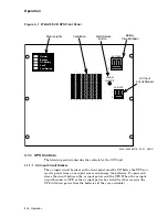
The following sections describe the indicators for the UPS unit.

3.1.2.1 Status Lights

The status lights, a column of five LEDs, show the UPS’s status. The print next

to each color coded status light briefly describes the condition that the status light

indicates.
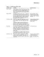
A description of each status light follows, along with a summary of the status

lights found in Table 3–1.

Normal Status Light

The green status light labeled "Normal" is lit when the UPS draws power from

the ac input line and the ac input power meets input specifications. The UPS is

in Normal mode when the ac line voltage is 208 Vac (+10%/-15%) and the output

voltage is 208 Vac (±2%) and locked to the line frequency.

Bypass Status Light

The yellow status light labeled "Bypass" is lit when the UPS switches to Bypass

mode. In Bypass mode the ac input bypasses the conditioning and battery

charging electronics, but is still available at the output receptacles. The power

available at the output receptacles is unconditioned and unregulated ac.

On Battery Status Light

The yellow status light labeled "On Battery" is lit when the UPS draws power

from the battery unit. This occurs when the ac input voltage drops below 177

Vac. The "On Battery" status also activates the audio alarm.
The battery backup is limited (back-up time is typically 10 minutes under full-

load). If the UPS does not return to normal operation before the batteries reach

a predetermined low-battery cutoff, the UPS will shut down and the load will be

dropped.

Fault Status Light

The red status light labeled "Fault" is lit when an overload, overtemperature, or

internal failure occurs. The "Fault" status also activates the audio alarm. If the

condition is harmful and persistent, the battery circuit breaker on the front panel

will trip. When the battery circuit breaker on the front panel trips, the UPS will

automatically transfer to Bypass mode.
If ac input power is available, the load will receive unconditioned and unregulated

ac power. If ac input power is not available, the load will be dropped.

Low Battery Status Light

The red status light labeled "Low Battery" is lit when the battery voltage drops

to a level where only 2 to 3 minutes of back-up time remains at full-load during a

prolonged ac line failure. The "Low Battery" status also causes the audio alarm

to change tone.

3–4 Operation

Содержание 2T-HA10F-CD

Страница 1: ...2T HA10F CD 3 6 kVA UninterruptiblePowerSystem OperatingInformation Order Number EK HA10F OP B01 Revision Update Information Revised August 1992 Digital Equipment Corporation...

Страница 2: ...of FCC rules which are designed to provide reasonable protection against such interference in a residential installation However there is no guarantee that interference will not occur in a particular...

Страница 3: ...t 2 2 3 Operation 3 1 Controls and Indicators 3 1 3 1 1 UPS Controls 3 2 3 1 1 1 AC Input Circuit Breaker 3 2 3 1 1 2 Battery Circuit Breaker 3 3 3 1 1 3 Alarm Silence Button 3 4 3 1 2 UPS Indicators...

Страница 4: ...hooting 5 1 5 3 Digital Services Troubleshooting 5 1 5 4 Periodic Battery Check 5 4 5 5 Storage Procedures 5 4 Figures 1 1 2T HA10F CD UPS Functional Diagram 1 2 3 1 2T HA10F CD UPS Front Panel 3 2 3...

Страница 5: ...WARNING The UPS battery unit contains batteries that are wired together to produce a high voltage Even with no external connections hazardous voltage exists inside the UPS battery unit that can cause...

Страница 6: ...TES Calls attention to information in text that may be of special importance CAUTIONS Calls attention to information in text that is essential in avoiding system or equipment damage WARNINGS Calls att...

Страница 7: ...ractions of the major components to accomplish this task When power for the loads comes from an ac input the UPS uses the following components to improve the quality of the power before it reaches the...

Страница 8: ...on transformer for output to the load When the batteries feed the UPS the bidirectional converter changes dc to ac and feeds the ac voltage to the isolation transformer for output to the load 1 1 2 Ba...

Страница 9: ...ade to the UPS unit Addition of a metal distribution panel box containing six 240 V output receptacles Addition of wiring from the UPS unit to the output receptacles Addition of ac input power wiring...

Страница 10: ...s than 3 total harmonic distortion Overload Rating 150 of full load for 30 seconds 2 3 Environmental Operating Temperature 0 C to 40 C 32 F to 104 F safety agency tested at 25 C 77 F Relative Humidity...

Страница 11: ...ight 16 84 cm 6 63 in Depth 63 83 cm 25 13 in Battery Front Panel Dimensions Width 48 26 cm 19 00 in Height 17 78 cm 7 00 in Battery Weight 67 kg 148 lb 2 6 Assembly Requirements in an H9702 Cabinet W...

Страница 12: ...breaker Indicators Status lights Normal Bypass On Battery ac input failure Fault includes overtemperature and overload Low Battery Audio alarm All of the controls and indicators are mounted on the fr...

Страница 13: ...following sections describe the controls for the UPS unit 3 1 1 1 AC Input Circuit Breaker The ac input circuit breaker on the front panel must be ON before the UPS can receive power from an ac input...

Страница 14: ...the unit see Figure 3 2 can deliver an electrical shock This condition can occur even when the UPS is disconnected from an ac power source and the ac input circuit breaker is OFF These high voltages c...

Страница 15: ...ut is still available at the output receptacles The power available at the output receptacles is unconditioned and unregulated ac On Battery Status Light The yellow status light labeled On Battery is...

Страница 16: ...S with discharged batteries If the batteries are allowed to remain discharged for long periods their life will be significantly shortened Table 3 1 Summary of Status Lights Name of Indicator Color of...

Страница 17: ...PS will not operate if the emergency shutdown plug is not installed or if the circuit between the terminals of the emergency shutdown plug is broken Pulling the emergency shutdown plug out of the emer...

Страница 18: ...peration Figure 3 2 2T HA10F CD UPS Rear View with FCC Shielding Removed MKV 040000216 02 91 RAGS Battery Unit Circuit Breaker Emergency Shutdown Plug Distribution Panel UPS Battery Unit Operation 3 7...

Страница 19: ...s to the ON position 3 4 2 Normal UPS Powerdown Use the following procedure to power down the UPS 1 Turn the individual load s off by placing their power switches to the OFF position 2 Place the batte...

Страница 20: ...ery circuit breaker located on the front panel of the UPS see Figure 3 1 to the OFF position The yellow Bypass status light on the UPS front panel should light to indicate that the UPS is operating in...

Страница 21: ...panel of the battery unit see Figure 3 2 to the OFF position Access to the battery unit circuit breaker requires the removal of an access plate located in the lower left rear of the cabinet 5 Unplug...

Страница 22: ...nge of the UPS unit to its shelf b Remove the two 6 32 screws that secure the battery unit to the bracket on the rear edge of its shelf 11 At the front of the H9702 cabinet remove the six 10 32 screws...

Страница 23: ...g power from the UPS or if the audio alarm is sounding and the Fault status light is lit call Digital Services for service When calling for service check the status lights on the UPS front panel and b...

Страница 24: ...correctly wired and installed see Section 3 3 If the UPS still does not function properly Digital Services should call Deltec Customer Service When calling for service check the status lights on the...

Страница 25: ...dio alarm The battery backup is limited backup time is typically 10 minutes under full load If the UPS does not return to normal operation before the batteries reach a predetermined low battery cutoff...

Страница 26: ...e following guidelines must be followed to protect the batteries 1 Charge the batteries fully before the UPS is stored by connecting the UPS to an ac source and operating it for 12 hours with all thre...

Отзывы: