ConnectCore 6UL SBC Pro interfaces
Communication interfaces
ConnectCore 6UL SBC Pro Hardware Reference Manual
21
Green LED Yellow LED Link/activity status
ON
OFF
10 Link/no activity
Blinking
OFF
10 Link/activity
ON
ON
100 Link/no activity
Blinking
ON
100 Link/activity
Ethernet PHY on/off
You can control Ethernet PHY power supply through a power switch to improve system power
management. ENET_PWR/IO26 signal from the I/O expander controls the state of the power switch.
Note
The PHYs share the same power switch, so they will always be switched on or off together.
Antenna connector
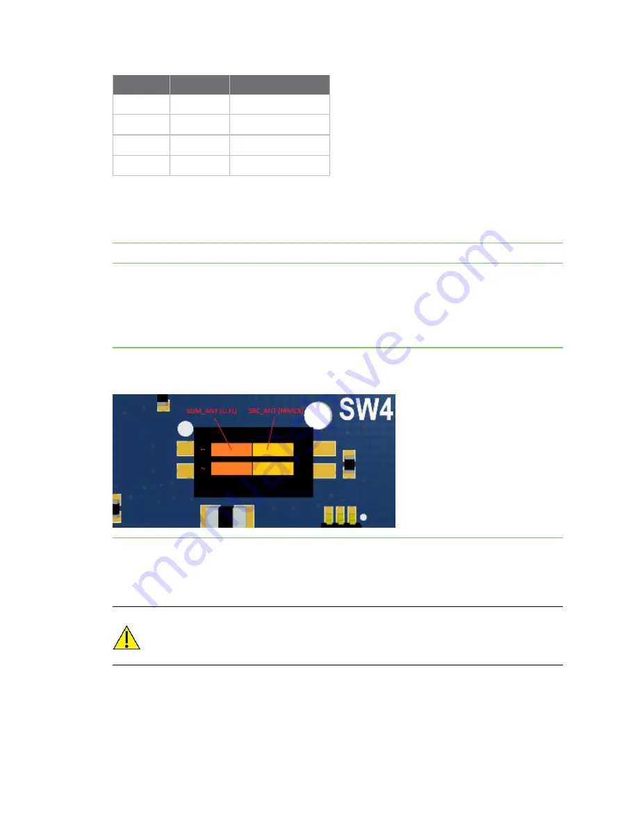
The ConnectCore 6UL SBC Pro includes an MMCX jack connector to support the wireless and
Bluetooth functionality available in the ConnectCore 6UL module. The connector for this antenna is
placed on the top-right side of the board.
Note
The double switch SW4 selects between the on-module antenna and the SBC antenna, so they
cannot be used simultaneously. The upper switch (1) selects the antenna (see picture below).
See
for a list of certificated antennas for the ConnectCore 6UL module.
This double switch SW4 also controls one of the RF kill signals: RF_KILL_HW#. Either this RF_KILL_HW#
or the internal RF_KILL_SW# (connected to the I/O expander RF_KILL_SW#/IO2 signal) must be
triggered to generate an RF kill event.
CAUTION!
The signals WLAN_RF_KILL#, BT_RF_KILL#, WLAN LED and BTLED are not yet
supported by the wireless baseband chip. Please contact Digi technical support at
before using these features.
USB Host
The ConnectCore 6UL SBC Pro offers support for four USB Host interfaces. Two of them are available
over a stackable dual USB A-type connector located on the front of the board. The third USB Host is


