91000741 A
3. Attach power supplies to all Modem/Xem modules, and the
PORTS/Xem modules that need auxiliary power, and then plug power
supplies into AC receptacles.
Turn on power to Modem/Xem modules using the power switch on
the left side of the module. (PORTS/Xem modules do not have a
power switch.)
Step Four: (Modem/Xem only) Set the speaker
control
Each Modem/Xem module has an internal speaker which will provide
audio output for any one of the modem ports in the module. You can
select the modem port that is to be connected to the speaker or select not
to use the speaker, via a DIP switch on the rear of the unit.
See the hardware information that came with your Modem/Xem for the
switch settings to use.
There is a speaker volume control on the left side of the module.
Step Five: Install peripheral cabling
Modem/Xem
Use standard RJ-11C telephone cables to connect Modem/Xem modules
to the telephone lines. Connect to analog telephone circuits only. Never
connect a modem module to a digital wall jack. Note that internal tele-
phone systems (such as a PBX, Private Branch Exchange), may be digi-
tal.
Also, the Modem/Xem modules are to be used only with public access
phone lines. Leased line operation is not supported.
Most phone systems are “loop start” but some are “ground start.” The
Modem/Xem will not operate with “ground start” phone systems.
PORTS/Xem
You can connect printers, terminals, modems (or any other standard EIA-
232 device to be controlled by applications on the computer) to the
PORTS/Xem modules. The cable connector on the peripheral end
depends on the requirements of the peripheral. The PORTS/Xem end of
the cable must fit either an RJ-45 or DB-25 connector, depending on the
module option you have.
The pin assignments for each type of PORTS/Xem connector are shown
on the back.
Refer to the CD-ROM for more detailed cabling information.
What Next?
At this point the hardware installation for your PORTS/Xem or
Modem/Xem system is complete. However, since the adapter must have
software downloaded to its internal RAM before it becomes functional,
you must next install the software driver for your operating system.
•
Read the instruction booklet for the CD-ROM that came with your
Xem system for instructions on installing software.
•
View the on-line documentation on the CD-ROM for more informa-
tion about AccelePort products.
The Digi logo and AccelePort are registered trademarks of Digi International. Xem,
PORTS/Xem, PORTS/8em, PORTS/16em, Modem/4em, Modem 8/em, and Modem/Xem
are trademarks of Digi International. All other brand and product names are trademarks of
their respective holders.
© Digi International Inc., 1998; All Rights Reserved; http://www.dgii.com
Information in this document is subject to change without notice and does not represent a
commitment on the part of Digi International.
Digi provides this document “as is”, without warranty of any kind, either expressed or
implied, including, but not limited to, the implied warranties of fitness or merchantability
for a particular purpose. Digi may make improvements and/or changes in this manual or in
the product(s) and/or the program(s) described in this manual at any time.
This product could include technical inaccuracies or typographical errors. Changes are peri-
odically made to the information herein; these changes may be incorporated in new editions
of the publication.
AccelePort
Xem System
Xem ISA Host Adapter
PORTS/8em, PORTS/16em Modules
Modem/4em, Modem/8em Modules
Hardware
Installation Guide
Introduction
An AccelePort
®
Xem
™
system consists of an Xem adapter coupled with
PORTS/Xem
™
modules (PORTS/8em
™
and PORTS/16em
™
) and/or
Modem/Xem
™
modules (Modem/4em
™
and Modem/8em
™
). The
PORTS/Xem modules easily expand the number of EIA-232 ports on
your computer, allowing you to cable additional peripheral devices such
as printers, terminals or modems to your computer. Modem/Xem mod-
ules contain either four or eight modems.
The Xem adapter can support up to four modules. Multiple modules of
either type can be linked in a chain to expand the number of EIA-232
ports and/or modems available.
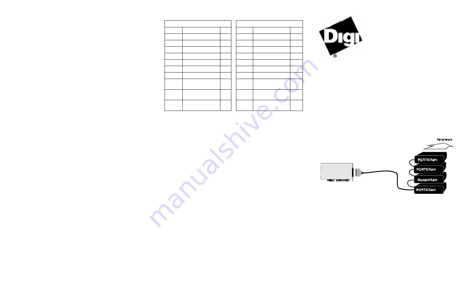
Figure 1.
Example setup
This installation guide describes how to plan your Xem system setup and
install the adapter and module hardware.
DB-25 Pin assignments
RJ-45 Pin Assignment
Signal
Description
Pin
Signal Description
Pin
GND
Chassis Ground
1*
RI
Ring Indicator
1
TxD
Transmitted Data
2
DSR
Data Set Ready
2†
RxD
Received Data
3
RTS
Request To Send
3
RTS
Request To Send
4
GND
Chassis Ground
4
CTS
Clear To Send
5
TxD
Transmitted Data
5
DSR
Data Set Ready
6
RxD
Received Data
6
SG
Signal Ground
7
SG
Signal Ground
7
DCD
Data Carrier
Detect
8
CTS
Clear To Send
8
DTR
Data Terminal
Ready
20
DTR
Data Terminal
Ready
9
RI
Ring Indicator
22
DCD
Data Carrier
Detect
10
* Chassis Ground is also available
on the connector shell
† Pin 2 can be configured for DCD
(through Digi software) if you want
to connect using an 8 pin
connector


