Saturn User Manual V1
Page 9
3.2 Feature Descriptions
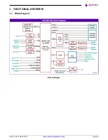
This section describes the key subsystems of the Saturn SBC.
3.2.1
Processor and Chipset
The Intel Atom® processor E390x series, formerly Apollo Lake, empowers real-time computing in digital
surveillance, new in-vehicle experiences, advancements in industrial and office automation, new solutions for retail
and medical, and more. These processors are based on the Goldmont architecture, utilizing Intel’s industry-leading
14 nm process technology.
Saturn SBC is based on Intel Atom processor x5-E3940. It is a quad core, 64-bit processor with a maximum
frequency of 1.8GHz.
3.2.2
Memory
The design employs DDR3L memory down configuration with ECC. The design supports single channel memory
interfaces with each up to 8GB capacity with ECC.
Channel consists of 8nos DDR3L 4Gbit chips with to support 4GB non-ECC memory and 9nos of DDR3L 8Gbit
chips with to support 8GB ECC memory configuration.
3.2.3
Ethernet
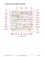
The board provides two Gigabit Ethernet ports. One port is derived directly from processor’s x1 PCIe lane using an
external I210 controller. The second port is realized from 1:4 PCIe switch lane using I210 controller. The board also
includes the necessary magnetics for both the ports. Ethernet interface is terminated on a latching connector, not
an RJ-45 jack.
On-board LEDs are provided for Link, Activity, and Speed. The LEDs are located along the board edge near the
Ethernet connector. The GbE ports use dual row,2x5 2mm pitch latching connectors. The connector does not
provide access to the LED signals.
3.2.4
SATA
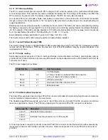
The board offers two SATA ports, both derived from the processor. One port is connected to an industry-standard
vertical 7pin SATA connector that accepts cables with latching. The second port is connected to M.2 2242 size, M-
key socket. SBC provides onboard M3 2mm spacer and M3 Screw to mount M.2 2242 sata SSD.
3.2.5
Display
The board offers three display output options: two HDMI and one LVDS.
The HDMI ports are directly from the processor and are made available on two separate dual row 2x10 2mm pitch
latching connectors. Two HDMI ports support HDMI 1.4b, maximum resolution is up to 3840x2160 @ 30Hz.
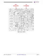
LVDS interface is obtained using an eDP to LVDS converter with the NXP PTN3460. The LCD backlight control is
provided by a PWM circuit. Both single channel and Dual channel LCDs are supported. VDD voltage can be selected
from 5V or 3.3V and Backlight Voltage can be selected from 12V or 5V.
LCD data signals are terminated on a 2x15 1mm pitch latching while LCD Backlight control & enable signals are
terminated on a 1x6 1.25mm pitch latching connector. LVDS display supports upto1920x1200 @ 60 Hz resolution
in dual LVDS bus mode.
3.2.6
Audio
The board provides HDA compatible audio controller ALC892. Audio I/O signals include stereo line in, stereo line
out and mono mic in. The analog audio signals are made available on a dual row 2x5 2mm pitch latching connector.

