Saturn User Manual V1
Page 39
13 DATA ACQUISITION CIRCUIT
13.1 Overview
Saturn contains a data acquisition subsystem consisting of A/D, D/A, digital I/O, and counter/timer features. The
circuit is controlled by an FPGA and connected to the SBC via the LPC bus.
The A/D section includes a 16-bit A/D converter, 16 analog input channels and a 2048-sample FIFO. Input ranges
are programmable, and the maximum sampling rate is 250 KHz. The D/A section include 4 16-bit D/A channels.
The digital I/O section includes up to 22 lines with programmable direction. The counter/timer section includes 32-
bit counter/timer to control A/D and a 32-bit counter/timer for user applications.
High-speed A/D sampling is supported with interrupts and a FIFO. The FIFO is used to store up to 2048 A/D
samples. An interrupt occurs when the FIFO reaches a user-selected threshold. Once the interrupt occurs, an
interrupt routine runs and reads the data out of the FIFO. In this way the interrupt rate is reduced by a factor equal
to the size of the FIFO threshold, enabling a faster A/D sampling rate and lower software overhead.
The A/D circuit uses the default settings of I/O address range 0x280-0x28F (base address 0x280). These settings
can be changed in the BIOS if needed.
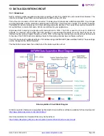
The illustration below shows the architecture of the data acquisition circuit.
Data Acquisition Circuit Block Diagram
All data acquisition features are supported by Diamond
’s Universal Driver software, available for free download at:
http://www.diamondsystems.com/products/dscud
User documentation for Universal Driver may be found here:
https://diamondsystems.gitbook.io/user-manuals/universal-driver/dscud-sw-user-manual


