Saturn User Manual V1.01
Page 19
6 I/O CONNECTORS
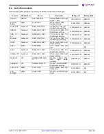
6.1 Connector Pin-out and Signal Description
6.1.1
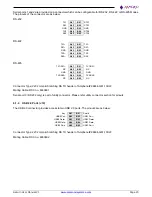
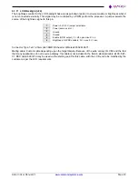
Power In (J8)
Input power may be supplied through the connector J8. All the required supply voltages for the board are derived
from the 5V input. The +12V input is optional and necessary only to drive LCD backlight.
Ground
1
2
+12V(Optional)
Ground
3
4
+5V
Ground
5
6
+5V
Ground
7
8
+5V
Connector used is a custom version of Samtec IPL1 with longer pins for better PCB soldering.
Mating Cable: DSC no. 6980512
The following diagram depicts the Front View of the Power Connectors. Note that this pinout is different compared
to Samtec datasheet.
Mating Side View of Power Connector
6.1.2
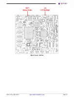
External Battery (J7)
To maintain the on-board real-time clock (RTC), Saturn has an on-board coin battery holder and by default a BR-
2032/BN is installed. It is possible to connect an external battery via connector J7 for longer battery life or long term
maintainability.
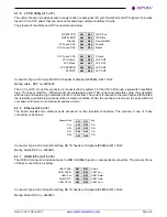
1
VBAT
2
Ground
VBAT = +3.0V
Connector used is 22-05-7025 right angle type friction lock pin header.
Mating cable: DSC 6980524
External Battery voltage specification: Typical 3.0V; Max: 3.2V; Min: 2.0V
The RTC current consumption is 6uA with RTC voltage at 3.0V while the system is in a mechanical off (G3) state
at room temperature. This data can be used to estimate the battery life. The voltage of the battery can affect the
RTC accuracy. In general, when the battery voltage decays, the RTC accuracy also decreases
Example batteries are: Duracell* 2032, 2025, or 2016 (or equivalent), which can give many years of operation.
Batteries are rated by storage capacity. The battery life can be calculated by dividing the capacity by the average
current required and considering external factors that effects the battery life. For example, if the battery storage
capacity is 19
0 mAh (assumed usable) and the average current required is 6 μA, the ideal battery life will be:
19
0,000 μAh/6 μA = 31,667 h = 3.6 years.
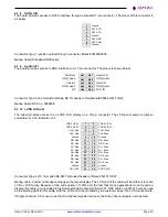
6.1.3
Serial Ports (J9)

