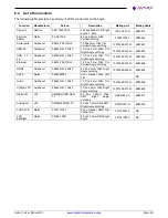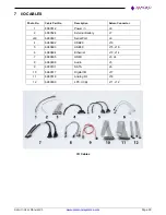
Saturn User Manual V1
Page 31
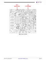
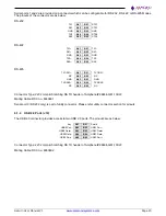
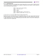
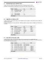
8.1 LVDS Backlight and LVDS VDD (JP1)
Jumper block JP1 configures the voltage supply for the LCD backlight and LVDS VDD.
By default, LVDS backlight is provided with +12V and the LVDS VDD is provided with 3.3V.
Position
Function
IN
OUT
12V*
LCD Backlight Voltage
12V
-
5V
LCD Backlight Voltage
5V
-
x
-
-
-
5V
LCD VDD Voltage
5V
-
3V3*
LCD VDD Voltage
3.3V
-
*Default Mode
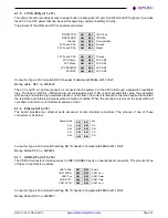
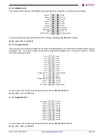
8.2 Digital IO and Address (JP2)
Jumper block JP2 configures the Voltage level for Digital IO and Pull up/down. It also selects the base address for
Data acquisition FPGA.
By default, Digital IO is 3.3V and pulled down. FPGA base address is set to 0x280 and USB3.0/2.0 Port 0 is Host
by default.
Position
Function
IN
OUT
ID
USB3.0/2.0 Port0 Mode
Host
Device
ADDR
FPGA Base Address
0x240
0x280
PD
DIO Pull Down Enable
Enabled
Disabled
PU
DIO Pull Up Enable
Enabled
Disabled
3V3
DIO Voltage Level
3.3V
-
5V
DIO Voltage Level
5V
-
*Default Mode
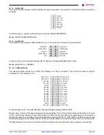
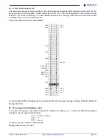
8.3 Serial Port Configuration (JP3)
Jumper block JP3 configures Serial Port1-2 protocol and termination select during RS422/485 mode.
By default, Serial ports are set to Internal loopback mode and terminations are disabled. The protocol selection is
superseded by DAQ software setting.
Position
Function
IN
OUT
SC1
Ser Port1-2 Mode select1
Refer Table Below
-
SC0
Ser Port1-2 Mode select0
Refer Table Below
RX2
Serial Port2 RX Termination
Enabled
Disabled
TX2
Serial Port2 TX Termination
Enabled
Disabled
RX1
Serial Port1 RX Termination
Enabled
Disabled
TX1
Serial Port1 TX Termination
Enabled
Disabled
*Default Mode

