Saturn User Manual V1
Page 26
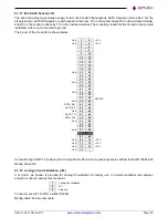
6.1.17 M.2 SATA Socket (J19)
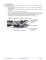
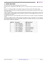
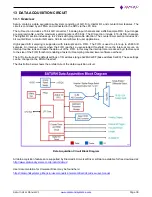
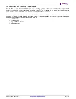
The board provides mass storage support via an M.2 socket that supports SATA modules of size 2242. For the
pinouts shown, all TX/RX signals are with respect to the host. TX on the socket drives RX on the installed module,
and RX on the socket is driven by TX on the installed module. The mounting standoff at the far end of the module
installation site is not connected to ground.
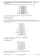
The pinout of the connector is shown below:
Gnd
1
2
+3.3V
Gnd
3
4
+3.3V
5
6
7
8
9
10
11
12
13
14
15
16
17
18
19
20
Gnd
21
22
23
24
25
26
Gnd
27
28
29
30
31
32
Gnd
33
34
35
36
37
38
DEVSLP
Gnd
39
40
41
42
SATA_RX-
43
44
Gnd
45
46
SATA_TX-
47
48
49
50
Gnd
51
52
53
54
55
56
Gnd
57
58
KEY
67
68
Gnd
69
70
+3.3V
Gnd
71
72
+3.3V
Gnd
73
74
+3.3V
Gnd
75
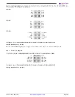
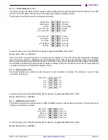
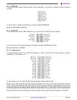
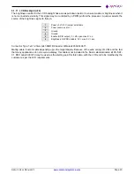
Connector Type: SMT 67 position with 0.5mm pitch for PCIe/104 one bank expansion of Samtec# ASP-129646-22
Mating Cable: NA
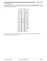
6.1.18 Analog Circuit Calibration (J23)
A 1x3 2mm pin header is provided for Analog IO calibration for factory use. In normal conditions the customer
should not need to access this connector.
1
Voltage for calibration
2
NC
3
Aground
Connector used is 1x3 2mm Vertical Header.
Mating cable: Factory test cable

