Saturn User Manual V1
Page 21
6.1.5
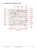
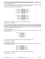
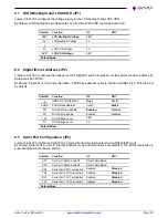
LPC & Utility (J11, J12)
The utility connector provides access to power button, reset signal, I2C port, Serial Port and LPC signals. It provides
fused 3.3V and 5V power that can be used for powering customer auxiliary circuitry.
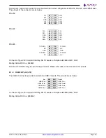
The pinouts of the Utility and LPC connectors are below:
RS232 TXD
A01
B01
I2C Clock
RS232 RXD
A02
B02
I2C Data
Ground
A03
B03
Power Button
5V Fused 0.5A
A04
B04
Ground
3.3V Fused 0.5A
A05
B05
Reset
3.3V Fused 0.5A
A01
B01
Ground
LPC Frame
A02
B02
LPC AD0
LPC Clock
A03
B03
LPC AD1
LPC SERIRQ
A04
B04
LPC AD2
PLTRST
A05
B05
LPC AD3
Connector Type: 2x5 2mm pitch RA TH header of Amphenol# 98464-G61-10ULF.
Mating cable: DSC no. 6980609
The 3.3V and 5V pin on this connector is connected to the system 3.3V and 5V rail through a polyswitch resettable
fuse. The fuse is rated for ~500mA maximum sustained current. If DC current exceeds this value, the polyswitch
will heat up and create a high resistance to limit current flow. The current is reduced to the level required to maintain
the resistance, maintaining a steady state protection condition. When the overload is removed, the polyswitch will
cool down and return to normal low-impedance mode
6.1.6
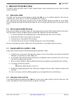
Ethernet (J13, J14)
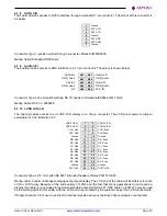
The board provides two ethernet ports accessed on two identical connectors. The pinouts of one of these
connectors is as below:
Chassis Gnd
A01
B01
Key
DA+
A02
B02
DA-
DB+
A03
B03
DB-
DC+
A04
B04
DC-
DD+
A05
B05
DD-
Connector Type: 2x5 2mm pitch latching RA TH header of Amphenol# 98464-G61-10ULF
Mating Cable: DSC no. 6980604
6.1.7
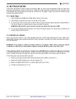
USB 3.0 Port (J15, J16)
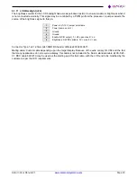
The USB3.0 connector provides access to USB 3.0/USB2.0 ports on two identical connectors. The pinouts of one
of these connectors is as below:
USB1 SSRX-
A01
B01
Shield
USB1 SSRX+
A02
B02
USB1 Pwr-
USB1 Pwr-
A03
B03
USB1 Data+
USB1 SSTX-
A04
B04
USB1 Data-
USB1 SSTX+
A05
B05
USB1 Pwr+
Connector Type: 2x5 2mm pitch latching RA TH header of Amphenol# 98464-G61-10ULF
Mating Cable: DSC no. 6980603

