Saturn User Manual V1
Page 12
3.2.15 Utility
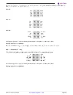
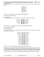
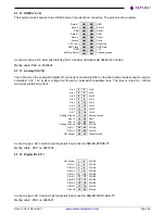
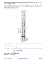
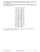
The board offers two 2x5 utility connectors, one with LPC bus interfaces for external IO expansion and another with
Serial Port (RS232), Power Button, Reset button and I2C interface.
Out of the two connectors, one provides 500mA fused 3.3V and 5V and the other connector provide 500mA fused
3.3V.
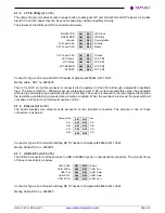
3.2.16 LED Indicators
The board provides the following LED indicators. All LEDs are located near to a board edge or their respective
features. The blue LED is located along the lower edge of the board. All LEDs are labeled in silkscreen with their
function.
PWRIN:
Green LED when Input supply 5VDC is applied
PWRON:
Green LED when board is powered on
BIOS:
Green, connected to a GPIO line on the processor; this LED is off during power-
up and is turned on in the BIOS to indicate a successful system BIOS startup.
Ethernet:
6 Green LEDs, 1 each for Link, Activity, and Speed per port
DONE:
FPGA is configured successfully.
USER:
Blue, User LED, controlled by processor FPGA
3.2.17 BIOS Features
The BIOS provides the following key features:
Boot from LAN (PXE) as well as USB and SATA ports
Free boot sequence configuration to allow different boot sequences as first, second and third boot
devices
Support multi display mode. HDMI and LVDS can be active simultaneously
Console (display and keyboard) redirection to one or more COM ports
DSC-configurable default settings in battery-less configurations; the necessary BIOS customization tool
must be provided
Customizable splash screen
Quiet boot option
Enable/disable for individual COM ports.
LPC interface for DAQ FPGA
Wake on LAN for on-board Ethernet, minicard socket
Single BIOS to support various memory configurations and processor variants
Integrated verb table for ALC892 Audio codec
BIOS LED to indicate successful BIOS initialization
Supports standard BIOS hotkey. This includes ESC key to enter BIOS menu etc
Password protection
Field upgradeable via a Shell/Windows utility

