Prometheus CPU User Manual V1.44
Page 35
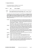
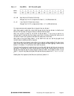
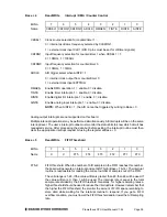
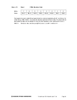
Base + 2
Read/Write
A/D Channel Register
Bit
No. 7 6 5 4 3 2 1 0
Name
H3 H2 H1 H0 L3 L2 L1 L0
H3 – H0
High channel of channel scan range
Ranges from 0 to 15 in single-ended mode, 0 - 7 in differential mode.
L3 - L0
Low channel of channel scan range
Ranges from 0 to 15 in single-ended mode, 0 - 7 in differential mode.
The high channel must be greater than or equal to the low channel.
When this register is written, the current A/D channel is set to the low channel, so that the next
time an A/D conversion is triggered the low channel will be sampled.
When this register is written to, the WAIT bit (Read Base + 3 bit 5) will go high for 10
microseconds to indicate that the analog input circuit is settling. During this time an A/D
conversion should not be performed because the data will be inaccurate.
After writing a new gain setting (Base + 3), the WAIT bit is also set, and the program must
monitor it prior to starting an A/D conversion.
The channel and gain registers can be written to in succession without waiting for the intervening
WAIT signal. Only one WAIT period must be observed between the last triggering condition (write
to Base + 2 or Base + 3) and the start of an A/D conversion.
The A/D circuit is designed to automatically increment the A/D channel each time a conversion is
generated. This enables the user to avoid having to write the A/D channel each time. The A/D
channel will rotate through the values between LOW and HIGH. For example, if LOW = 0 and
HIGH = 3, the A/D channels will progress through the following sequence: 0, 1, 2, 3, 0, 1, 2, 3, 0,
1, ….
Reading from this register returns the value previously written to it.
Содержание PROMETHEUS PR-Z32-E-ST
Страница 73: ...Prometheus CPU User Manual V1 44 Page 73...


