JetBox-FloydSC User Manual rev 0.1
Page 16
Serial Ports
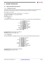
The system provides two serial ports. One of the serial ports is dedicated to RS232 protocol and the second port
can be configured to either RS232 or RS485 based on Jumper settings. The pinouts for different protocols are as
follows:
RS-232
RS-485
No Connect
6
1
No Connect
No Connect
6
1
No Connect
RTS
7
2
RX
TX-
7
2
No Connect
CTS
8
3
TX
No Connect
8
3
TX+
No Connect
9
4
No Connect
No Connect
9
4
No Connect
5
Ground
5
Ground
Connector Part No
: DB9 Male
DSC Mating cable
: Standard DB9 female-to-female cable
Digital I/O
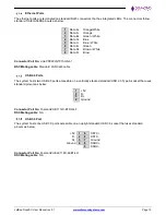
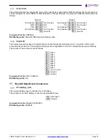
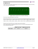
The system provides access to 8 digital I/O pins on the front panel, terminated on a 11-position, 3.5mm pitch
screw terminal connector. These digital I/O signals are configurable to 3.3V/5V configurable via jumper settings.
The pinouts of the connector are as follows:
1
DIO 0
2
DIO 1
3
DIO 2
4
DIO 3
5
DIO 4
6
DIO 5
7
DIO 6
8
DIO 7
9
+3.3V or +5V
10
Ground
11
Ground
Connector Part No
: TE# 1-284414-1
DSC Mating cable
: NA
FloydSC Base Board Connectors
RTC Battery (J18)
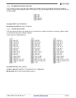
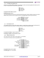
The external battery input is intended for a 3V battery.
The pinouts for the RTC Battery connector are specified below.
1
RTC BAT +
2
Ground
Connector Part No
: Molex# 0022035025
DSC Mating cable
: 6980524

