background image


1

4

5

30sec.

For

A

mA

15 min.

every

MAX

20A

A

A

2

3

¦¸

F

+-

V

7

8

6

HOLD

F

C

VAC or VDC. 

This  symbol  adjacent  to  one  or  more 

terminals  identifies  them  as  being 

associated  with  ranges  that  may,  in 

normal 

use, 

be 

subjected 

to 

particularly  hazardous  voltages.  For 

maximum safety, the meter and its test 

leads  should  not  be  handled  when 

these terminals are energized. 


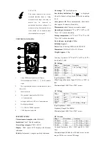
CONTROLS AND JACKS 


1.


Large 2000 count Liquid Crystal Display   

With  backlight  and  HOLD, 

,  BAT  symbolic 

signs. 

2.


Power pushbutton: the power button turns the meter           

ON or OFF. 

3.


Function switch 

4.


20A (positive) input jack for 20A DC or 

  AC measurements. 

5.


mA input jack for mA DC or AC measurements 

6.


Backlight pushbutton. 

7.


V,

Ω

,CAP, Hz, TEMP. input jack 

8.


COM (negative) input jack. 


SPECIFICATIONS 

The instrument complies with: 

EN61010-1. 

Insulation: 

Class2, Double insulation. 

Overvoltage category: 

CATII - 1000V. 

Display:

  2000  counts  LCD  display  with  function 

indication. 

Polarity:

 Automatic, (-) negative polarity indication. 

Overrange:

 “OL” mark indication. 

Low  battery  indication:

  The  “          ”  is  displayed 

when  the  battery  voltage  drops  below  the  operating 

level. 

Auto  power  off:

  Meter  automatically  shuts  down 

after approx. 10 minutes of inactivity. 

Measurement rate: 

2 times per second, nominal. 

Operating environment:

 0 oC to 50 oC (32 oF to 122 

oF) at < 70 % relative humidity. 

Storage temperature:

 -20 oC to 60 oC (-4 oF to 140 

oF) at < 80 % relative humidity. 

For inside use, max height: 

2000m 

Pollution degree:

 2


Power:

 One 9V battery, NEDA 1604, IEC 6F22. 

Dimensions:

 182 (H) x82 (W) x 55 (D) mm 

Weight: Approx.:

 360g. 


Accuracy is given at 18 oC to 28 oC (65 oF to 83 oF), 

less than 70 % RH 

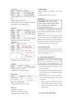
DC Voltage


Range 

Resolution 

Accuracy 

200.0mV 

0.1mV 

+0.5% of rdg + 2 dgts 

2.000V 

1mV 

20.00V 

10mV 

200.0V 

100mV 

1000V 

1V 

+0.8% of rdg + 2 dgts 

Input Impedance: 10M

200mV  range  Maximum  Input:  250V  dc  or  250V  ac 

rms. 

Maximum Input: 1000V dc or 700V ac rms. 


AC Voltage


Range 

Resoluti
on 

Accuracy 

2.000V 

1mV 

+1.0% of rdg + 3 dgts 

20.00V 

10mV 

200.0V 

100mV 

700V 

1V 

+1.2% of rdg + 5 dgts 

Input Impedance: 10M

Frequency Range:50 to 400Hz   

Maximum Input: 1000V dc or 700V ac rms. 


DC Current


Range 

Resolution 

Accuracy 

2.000mA 

1uA 

+1.0% of rdg + 3 dgts 

200.0mA 

100uA 

+1.5% of rdg + 3 dgts 

20.00A 

10mA 

+2.5% of rdg + 10 dgts 

Overload  Protection:  0.2A  /  250V  and  20A  /  250V 

Fuse. 

Maximum Input: 200mA dc or 200mA ac rms on mA 

ranges, 20A dc or ac rms on 20A range. 

Содержание 9908

Страница 1: ...oltage which exceeds the limits of the multimeter may damage the meter and expose the operator to a shock hazard Always recognize the meter voltage limits as stated on the front of the meter Never apply voltage or current to the meter that exceeds the specified maximum SAFETY SYMBOLS This symbol adjacent to another symbol terminal or operating device indicates that the operator must refer to an ex...

Страница 2: ...oltage drops below the operating level Auto power off Meter automatically shuts down after approx 10 minutes of inactivity Measurement rate 2 times per second nominal Operating environment 0 oC to 50 oC 32 oF to 122 oF at 70 relative humidity Storage temperature 20 oC to 60 oC 4 oF to 140 oF at 80 relative humidity For inside use max height 2000m Pollution degree 2 Power One 9V battery NEDA 1604 I...

Страница 3: ...c or ac rms OPERATION WARNING Risk of electrocution High voltage circuits both AC and DC are very dangerous and should be measured with great care If 1 appears in the display during a measurement the value exceeds the range you have selected Change to a higher range NOTE On some low AC and DC voltage ranges with the test leads not connected to a device the display may show a random changing readin...

Страница 4: ...ositive side of the circuit 6 Apply power to the circuit 9 Read the current in the display The display will indicate the proper decimal point value AC CURRENT MEASUREMENTS WARNING To avoid electric shock do not measure AC current on any circuit whose voltage exceeds 250V AC CAUTION Do not make current measurements on the 20A scale for longer than 30 seconds Exceeding 30 seconds may cause damage to...

Страница 5: ... evaluated as follows A If one reading shows a value and the other reading shows 1 the diode is good B If both readings show 1 the device is open C If both readings are very small or 0 the device is shorted NOTE The value indicated in the display during the diode check is the forward voltage FREQUENCY MEASUREMENT 1 Set the function switch to the 20KHz position 2 Insert the black test lead banana p...

Страница 6: ...ny source of voltage before removing the battery door 1 Disconnect the test leads from the meter 2 Open the battery door by loosening the screw using a Phillips head screwdriver 3 Insert the battery into battery holder observing the correct polarity 4 Put the battery door back in place Secure with the one screw WARNING To avoid electric shock do not operate the meter until the battery door is in p...

Отзывы: