SH960MD-CM236/QM170/HM170
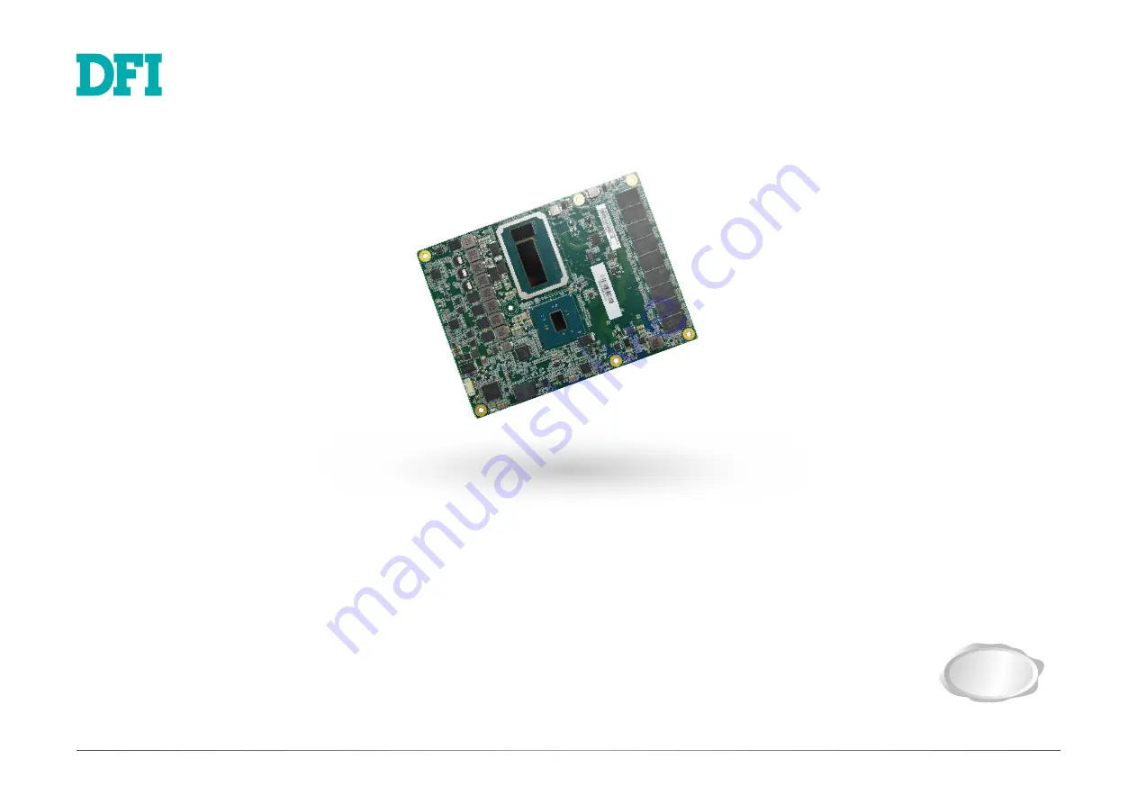
COM Express Basic Module
User’s Manual
A-520-M-2002
Preliminary
Version
Страница 1: ...SH960MD CM236 QM170 HM170 COM Express Basic Module User s Manual A 520 M 2002 Preliminary Version Preliminary Version ...
Страница 2: ... FCC and DOC Statement on Class B This equipment has been tested and found to comply with the limits for a Class B digital device pursuant to Part 15 of the FCC rules These limits are designed to provide reason able protection against harmful interference when the equipment is operated in a residential installation This equipment generates uses and can radiate radio frequency energy and if not ins...
Страница 3: ...ons 22 SPI Signals Descriptions 22 VGA Signals Descriptions 22 DDI Signals Descriptions 23 Serial Interface Signals Descriptions 25 I2C Signal Descriptions 25 Miscellaneous Signal Descriptions 26 Power and System Management Signals Descriptions 26 Thermal Protection Signals Descriptions 27 SMBUS Signals Descriptions 27 GPIO Signals Descriptions 27 Power and GND Signal Descriptions 28 Module type S...
Страница 4: ...ponents or devices even before installing them in your system unit Static electrical discharge can damage computer components without causing any signs of physical damage You must take extra care in han dling them to ensure against electrostatic build up 1 To prevent electrostatic build up leave the system board in its anti static bag until you are ready to install it 2 Wear an antistatic wrist st...
Страница 5: ...r in accordance with the sales region or models in which it was sold For more information about the standard package in your region please contact your dealer or sales representative Before Using the System Board Before using the system board prepare basic system components If you are installing the system board in a new system you will need at least the following inter nal components Monitor USB ...
Страница 6: ... 1920x1200 60Hz LVDS dual channel 24 bit resolution up to 1920x1200 60Hz HDMI resolution up to 4096x2160 24Hz or 2560x1600 60Hz DVI resolution up to 1920x1200 60Hz DP eDP resolution up to 4096x2304 60Hz Triple Displays VGA LVDS DDI VGA DDI1 DDI2 eDP 2 DDI available upon request EXPANSION Interface 1 x PCIe x16 or 2 x PCIe x8 Gen 3 8 x PCIe x1 or 2 x PCIe x4 or 4 x PCIe x2 Gen 3 1 x LPC 1 x I2 C 1 ...
Страница 7: ...oard LAN port or via a PCI LAN card that uses the PCI PME Power Man agement Event signal However if your system is in the Suspend mode you can power on the system only through an IRQ or DMA interrupt USB The system board supports the new USB 3 0 It is capable of running at a maximum transmis sion speed of up to 5 Gbit s 625 MB s and is faster than USB 2 0 480 Mbit s or 60 MB s and USB 1 1 12Mb s U...
Страница 8: ...re makeover The COM Express module can be replaced when there is only need to upgrade for higher computing performance while the carrier board can be redesigned when there is solely change in applica tion COM Express also comes in different form factors and signal Types cut out for different scales and aspects of the system s application Detailed specifications of COM Express are available on the ...
Страница 9: ...r components Perform installation procedures at an ESD workstation only If such a station is not available you can provide some ESD pro tection by wearing an antistatic wrist strap and attaching it to a metal part of the system chassis If a wrist strap is unavailable establish and maintain contact with the system chassis throughout any procedures requiring ESD protection Intel CM236 QM170 HM170 In...
Страница 10: ...on the same channel DIMMs in a channel can be identi cal or completely different However we highly recommend using identical DIMMs Not all slots need to be populated Dual Channel DIMMs of the same memory configuration are on different channels DDR4 Carrier Board COM Express module CPU Cooler X Assembly A CPU cooler is included in the standard package The CPU cooler contains six spring screws and s...
Страница 11: ...loft from the stand offs at this moment 3 At the long edge away from the connector apply firm pressure with another hand onto the module and press it onto the carrier board until the module is against the remaining three stand offs Please also maintain the pressure described in the previous step the whole time Board to board connector on COM Express module A B C D D E F A B C E F Board to board co...
Страница 12: ...ld also sit directly on top of the CPU and PCH chip sets on the module Use a screw driver to fasten the screws in the order as numbered below By following the order the risk of damaging the component is significantly re duced 1 6 3 2 5 4 1 6 3 2 5 4 X I O Connectors CPU Fan Pin Assignment 1 Ground 2 Power 3 Sense CPU Fan 3 pin Fan Pin Assignment The fan connector is used to connect to cooling fans...
Страница 13: ..._SDIN1 A30 AC HDA _RST B30 AC HDA _SDIN0 A31 GND FIXED B31 GND FIXED A32 AC HDA _BITCLK B32 SPKR A33 AC HDA _SDOUT B33 I2C_CK A34 BIOS_DIS0 B34 I2C_DAT A35 THRMTRIP B35 THRM A36 USB6 B36 USB7 A37 USB6 B37 USB7 A38 USB_6_7_OC B38 USB_4_5_OC A39 USB4 B39 USB5 A40 USB4 B40 USB5 A41 GND FIXED B41 GND FIXED A42 USB2 B42 USB3 A43 USB2 B43 USB3 A44 USB_2_3_OC B44 USB_0_1_OC A45 USB0 B45 USB1 A46 USB0 B46...
Страница 14: ...2 USB_SSTX3 C13 USB_SSRX3 D13 USB_SSTX3 C14 GND D14 GND C15 NC D15 DDI1_CTRLCLK_AUX C16 NC D16 DDI1_CTRLDATA_AUX C17 RSVD D17 RSVD Row C Row D C18 RSVD D18 RSVD C19 PCIE_RX6 D19 PCIE_TX6 C20 PCIE_RX6 D20 PCIE_TX6 C21 GND FIXED D21 GND FIXED C22 PCIE_RX7 D22 PCIE_TX7 C23 PCIE_RX7 D23 PCIE_TX7 C24 DDI1_HPD D24 RSVD C25 NC D25 RSVD C26 NC D26 DDI1_PAIR0 C27 RSVD D27 DDI1_PAIR0 C28 RSVD D28 RSVD C29 N...
Страница 15: ...C88 PEG_RX11 D88 PEG_TX11 C89 PEG_RX11 D89 PEG_TX11 C90 GND FIXED D90 GND FIXED C91 PEG_RX12 D91 PEG_TX12 C92 PEG_RX12 D92 PEG_TX12 C93 GND D93 GND C94 PEG_RX13 D94 PEG_TX13 C95 PEG_RX13 D95 PEG_TX13 C96 GND D96 GND C97 RSVD D97 RSVD C98 PEG_RX14 D98 PEG_TX14 C99 PEG_RX14 D99 PEG_TX14 C100 GND FIXED D100 GND FIXED C101 PEG_RX15 D101 PEG_TX15 C102 PEG_RX15 D102 PEG_TX15 C103 GND D103 GND C104 VCC_1...
Страница 16: ...00BASE T 100BASE TX 10BASE T MDI 0 B1_DA TX TX MDI 1 B1_DB RX RX MDI 2 B1_DC MDI 3 B1_DD Media Dependent Interface MDI differential pair 0 GBE0_MDI0 A12 I O Analog 3 3V max Suspend GBE0_MDI1 A10 I O Analog 3 3V max Suspend Media Dependent Interface MDI differential pair 1 GBE0_MDI1 A9 I O Analog 3 3V max Suspend GBE0_MDI2 A7 I O Analog 3 3V max Suspend Media Dependent Interface MDI differential pa...
Страница 17: ...r Serial ATA channel 1 Receive input differential pair SATA1_RX B20 I SATA AC coupled on Module AC Coupling capacitor SATA2_TX A22 O SATA AC coupled on Module AC Coupling capacitor Serial ATA or SAS Channel 2 transmit differential pair Serial ATA channel 2 Transmit output differential pair SATA2_TX A23 O SATA AC coupled on Module AC Coupling capacitor SATA2_RX A25 I SATA AC coupled on Module AC Co...
Страница 18: ...IE AC coupled off Module PCI Express Differential Receive Pairs 3 PCIe channel 3 Receive Input differential pair PCIE_RX3 B59 PCIE_TX4 A55 O PCIE AC coupled on Module AC Coupling capacitor PCI Express Differential Transmit Pairs 4 PCIe channel 4 Transmit Output differential pair PCIE_TX4 A56 PCIE_RX4 B55 I PCIE AC coupled off Module PCI Express Differential Receive Pairs 4 PCIe channel 4 Receive I...
Страница 19: ...coupled off Module PCI Express Graphics receive differential pairs 4 PEG channel 4 Receive Input differential pair PEG_RX4 C66 PEG_TX5 D68 O PCIE AC coupled on Module AC Coupling capacitor PCI Express Graphics transmit differential pairs 5 PEG channel 5 Transmit Output differential pair PEG_TX5 D69 PEG_RX5 C68 I PCIE AC coupled off Module PCI Express Graphics receive differential pairs 5 PEG chann...
Страница 20: ...l pair PEG_TX15 D102 PEG_RX15 C101 I PCIE AC coupled off Module PCI Express Graphics receive differential pairs 15 PEG channel 15 Receive Input differential pair PEG_RX15 C102 PEG_LANE_ RV D54 I CMOS 3 3V 3 3V PU 10KΩ to 3V3 PCI Express Graphics lane reversal input strap Pull low on the Carrier board to reverse lane order PCI Express Graphics lane reversal input strap Pull low on the carrier board...
Страница 21: ..._6_7_OC A38 I CMOS 3 3V Suspend 3 3V PU 10KW to 3 3V Suspend USB over current sense USB channels 6 and 7 A pull up for this line shall be present on the Module An open drain driver from a USB current monitor on the Carrier Board may drive this line low Do not pull this line high on the Carrier Board USB over current sense USB ports 6 and 7 USB_SSTX0 D4 O PCIE AC coupled on Module AC Coupling capac...
Страница 22: ...S_B_CK shall have 100Ω terminations across the pairs at the destination These terminations may be on the Carrier Board if the Carrier Board implements a LVDS deserializer on board LVDS channel B differential signal pair 0 LVDS_B0 B72 LVDS_B1 B73 O LVDS LVDS LVDS channel B differential signal pair 1 LVDS_B1 B74 LVDS_B2 B75 O LVDS LVDS LVDS channel B differential signal pair 2 LVDS_B2 B76 LVDS_B3 B7...
Страница 23: ...ard SPI sourced from Module nominally 3 3V The Module shall provide a minimum of 100mA on SPI_POWER Carriers shall use less than 100mA of SPI_POWER SPI_POWER shall only be used to power SPI devices on the Carrier BIOS_DIS0 A34 I CMOS NA PU 10KΩ to 3V3 Suspend Selection straps to determine the BIOS boot device The Carrier should only float these or pull them low please refer to COM Express Module B...
Страница 24: ...DVO SDVO1_FLDSTALL differential pair Serial Digital Video Field Stall input differential pair NA DDI1_PAIR6 C16 NC NA DDI1_ CTRLCLK_ AUX D15 I O PCIE AC coupled on Module PD 100K to GND S W IC between Rpu PCH DDI for Display Port DP1_AUX Differetial pairs DP AUX function if DDI1_DDC_AUX_SEL is no connect Half duplex bi directional AUX channel for services such as link configuration or maintenance ...
Страница 25: ...is no connect Half duplex bi directional AUX channel for services such as link configuration or maintenance and EDID access DP2_AUX for DP I O OD CMOS 3 3V 3 3V PU 2 2K to 3 3V PU 100K to 3 3V S W IC between 2 2K 100K resistor DDI for HDMI DVI HDMI2_CTRLDATA HDMI DVI I2C CTRLDATA if DDI2_DDC_AUX_SEL is pulled high HDMI2_CTRLDATA for HDMI or DVI DDI2_HPD D44 I CMOS 3 3V 3 3V PD 1M to GND DDI for Di...
Страница 26: ... function of DDI3_CTRLCLK_AUX and DDI3_CTRLDATA_AUX This pin shall have a 1M pull down to logic ground on the Module If this input is floating the AUX pair is used for the DP AUX signals If pulled high the AUX pair contains the CRTLCLK and CTRLDATA signals Selects the function of DP3 AUX Low or HDMI3 DDC CLK DATA High The DDC_AUX_SEL pin should be routed to pin 13 of the DisplayPort connector to e...
Страница 27: ...le may be used Reset button input Active low request for Module to reset and reboot May be falling edge sensitive For situations when SYS_RESET is not able to reestablish control of the system PWR_OK or a power cycle may be used CB_RESET B50 O CMOS 3 3V Suspend 3 3V PD 100KΩ to GND Reset output from Module to Carrier Board Active low Issued by Module chipset and may result from a low SYS_RESET inp...
Страница 28: ...o initiate thermal throttling THRMTRIP A35 O CMOS 3 3V 3 3V PU 10KΩ to 3 3V Active low output indicating that the CPU has entered thermal shutdown Thermal Trip indicates an overheating condition of the processor If THRMTRIP goes active the system immediately transitions to the S5 State Soft Off SMBUS Signals Descriptions Signal Pin Pin Type Pwr Rail Tolerance SH960MD PU PD Module Base Specificatio...
Страница 29: ...ription COM Express Carrier Design Guide R2 0 Description TYPE0 C54 PDS N C TYPE2 TYPE1 TYPE0 X X X pin out Type 1 NC NC NC pin out Type 2 NC NC GND pin out Type 3 no IDE NC GND NC pin out Type 4 no PCI NC GND GND pin out Type 5 no IDE no PCI GND NC NC pin out Type 6 no IDE no PCI The Type pins indicate the COM Express pin out type of the Module To indicate the Module s pin out type the pins are e...
Страница 30: ... off In general the information stored in the CMOS RAM of the EEPROM will stay unchanged unless a configuration change has been made such as a hard drive replaced or a device added It is possible that the CMOS battery will fail causing CMOS data loss If this happens you need to install a new CMOS battery and reconfigure the BIOS settings Default Configuration Most of the configuration settings are...
Страница 31: ...UCE Project Name BIOS Version Processor Type EC Ver CPUID CPU Speed CPU Stepping L1 Data Cache L1 Instruction Cache L2 Cache L3 Cache Number Of Processors Microcode Rev GOP Ver Total Memory System Memory Speed SODIMM 0 PCH Rev SKU Intel ME Version SKU System Time System Date Security Advanced Boot Exit Main X Advanced The Advanced menu allows you to configure your system for basic operation Some e...
Страница 32: ...ion Wake On LAN Disabled After G3 Always Off Advanced X Advanced InsydeH2O Setup Utility Rev 5 0 F1 Help Esc Exit Select Item Select Item F5 F6 Change Values Enter Select SubMenu F9 Setup Defaults F10 Save and Exit CPU Configuration C States Enable or disable CPU Power Management It allows CPU to go to C States when it s not 100 utilized Intel R SpeedStep tm This field is used to enable or disable...
Страница 33: ... and numbers 1 8 and 2 4 2 8 or 1 16 LVDS Panel Supported Enable or disable PTN3460 s function to support LVDS panel Select which of IGFX PEG PCI Graphics device should be Primary Display or select SG for Switchable Gfx Video Configuration Primary Display Internal Graphics Panel Color Depth LCD Panel Type PEG LinkWidth LVDS Panel Supported Advanced Auto Auto 24 Bit 1024X768 PEG 1 16 Normal PWM Mod...
Страница 34: ...Installed Enabled Not Installed Enabled Not Installed Enabled Enabled SATA Controller s Enable or disable the Serial ATA controller This following fields will only be displayed when this field is enabled SATA Mode Selection The mode selection determines how the SATA controller s operates AHCI This option allows the Serial ATA controller s to use AHCI Advanced Host Control ler Interface RAID This o...
Страница 35: ... port PCIe Speed Select PCIe Speed of the current port AUTO Gen1 Gen2 or Gen3 Gen 3 is only available for the PCIE1 port This field may not appear when the speed of the port is not configurable X Advanced ME Configuration Configure Management Engine related settings in this page Me Fw Image Re Flash Enabled Allow the user to re write the ME firmware Disabled ME firmware re write is not allowed Ins...
Страница 36: ...valid numerals and press Enter again to select from Yes to save or No to abort SIO ITE8528E PC Health Status COM Port 1 Base I O Address Interrupt COM Port 2 Base I O Address Interrupt WDT COUNTER PC Health Status Configure Serial port us ing options Disable No Configuration Enable User Configuration This section displays the system s health information i e voltage readings CPU and system temperat...
Страница 37: ...Setup Utility Rev 5 0 F1 Help Esc Exit Select Item Select Item F5 F6 Change Values Enter Select SubMenu F9 Setup Defaults F10 Save and Exit Select Power on state for Numlock Numlock Boot Type Network Stack PXE Boot capability USB Boot EFI Legacy Main Advanced Security Exit On Dual Boot Type Disabled Disabled Enabled Boot Numlock Select the power on state for numlock Boot Type Select the boot type ...
Страница 38: ...ve CD DVD ROM Drive USB Others Arrange the priority of the storage devices in each category The submenu will not be displayed when there is no available storage device of the type Legacy Configure boot priorities in this submenu Re arrange the order by pressing or F5 F6 to move the highlighted item down up the priority list This field is only available when Boot Type is set to Legacy Boot Type or ...
Страница 39: ...ot follow the methods above the Intel Management Engine will not be up dated and will cease to be effective Note a You can take advantage of flash tools to update the default configuration of the BIOS SPI ROM to the latest version anytime b When the BIOS IC needs to be replaced you have to populate it properly onto the system board after the EEPROM programmer has been burned and follow the technic...
Страница 40: ...ur optical drive or executing your DVD image the System Utility auto run menu may pop up Click on the utility or driver that is to be installed on the system Please refer to the following sections that correspond to your selection for more information X Intel Chipset Software Installation Utility The Intel Chipset Software Installation Utility is used for updating Windows INF files so that the Int...
Страница 41: ...Drivers 1 Setup is now ready to install the graphics driver Click Next 2 Read the license agreement then click Yes By default the Automatically run WinSAT and enable the Windows Aero desktop theme is enabled With this enabled after installing the graphics driver and the system rebooted the screen will turn blank for 1 to 2 minutes while WinSAT is running before the Windows 10 desktop appears The b...
Страница 42: ...n tips then click Next 5 Click Yes I want to restart this computer now then click Fin ish Restarting the system will al low the new software installa tion to take effect X Realtek Audio Drivers 2 Click Yes I want to restart my computer now then click Fin ish Restarting the system will al low the new software installa tion to take effect 1 Setup is ready to install the driver Click Next ...
Страница 43: ... the driver Click Next 2 Click I accept the terms in the license agreement then click Next 3 Select the program features you want installed then click Next 5 The step displays the installing status in the progress 4 Click Install to begin the in stallation 6 After completing installation click Finish ...
Страница 44: ...driver Click Next 2 Read the license agreement then tick I accept the terms in the License Agreement Click Next 3 Click Next to install to the default folder or click Change to choose another destination folder 4 Please wait while the product is being installed 5 After completing installation click Finish ...
Страница 45: ...er management for the storage subsystem 2 Read the license agreement and click I accept the terms in the License Agreement Then click Next 1 Setup is ready to install the util ity Click Next 3 Go through the readme docu ment to view system require ments and installation informa tion then click Next 5 Confirm the installation and click Next 4 Click Next to install to the default folder or click Cha...
Страница 46: ...MD 6 Click Yes I want to restart this computer now to complete the installation and then click Fin ish X Adobe Acrobat Reader 9 3 1 Click Next to install or click Change Destination Folder to select another folder 2 Click Install to begin installa tion ...
Страница 47: ...46 Chapter 4 SUPPORTED SOFTWARE User s Manual SH960MD 3 Setup is now installing the driver 4 Click Finish to exit installa tion ...