19
Chapter 2
HARDWARE INSTALLATION
User's Manual |
EB100-KU
1
1
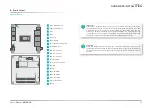
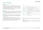
The Serial ATA (SATA) connectors are used to connect the Serial ATA device. SATA 3.0 is sup-
ported by the five SATA ports and provides data rate up to 6Gb/s. Connect one end of the Se-
rial ATA cable to a SATA connector and the other end to your Serial ATA device.
There is a converter cable for converting the 20-pin board connector to a common 7-pin + 15-
pin SATA data + power connector.
BIOS Setting
Configure the Serial ATA drives in the "Advanced" menu (“SATA Configuration” submenu) of the
BIOS. Refer to chapter 3 for more information.
SATA (Serial ATA) Connector
X
I/O Ports
Battery
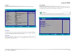
The external lithium ion battery supplies power to the real-time clock and CMOS memory as an
auxiliary source of power when the main power is shut off.
Safety Measures
• There exists explosion hazard if the battery is incorrectly installed.
• Replace only with the same or equivalent type recommended by the manufacturer.
• Dispose of used batteries according to local ordinances.
Battery
External Battery
Connect to board
X
I/O Ports
3.3V
2 1
GND
20-pin connector
7+15 pin connector
1
GND
S1
GND
2
GND
S2
TP+
3
GND
S3
TP-
4
GND
S4
GND
5
GND
S5
RP-
6
N.C.
S6
RP+
7
+5V
S7
GND
8
+5V
P1
N.C.
9
+5V
P2
N.C.
10
+5V
P3
N.C.
11
+5V
P4
N.C.
12
N.C.
P5
N.C.
13
N.C.
P6
N.C.
14
GND
P7
+5V
15
RP+
P8
+5V
16
RP-
P9
+5V
17
GND
P10
GND
18
TP-
P11
GND
19
TP+
P12
GND
20
GND
P13
N.C.
P14
N.C.
P15
N.C.
SATA Pin Assignment


