25
Chapter 2
HARDWARE INSTALLATION
User's Manual |
CS103
X
Internal I/O Connectors
LVDS Panel
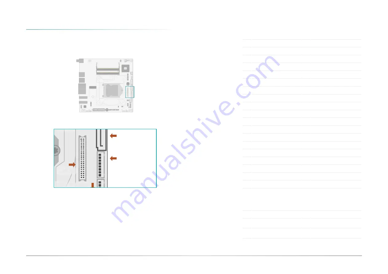
The system board allows you to connect a LCD Display Panel by means of the LVDS LCD panel
connector and the LCD/Inverter power connector. These connectors transmit video signals and
power from the system board to the LCD Display Panel.
Jumper Setting
The power voltage of the LCD panel, inverter power, and backlight power is configured via
jumper settings as previously instructed in this chapter.
LVDS LCD Panel
Pin Assignment
LCD/Inverter Power
Pin Assignment
Pin Function
Pin Function
1
GND
2
GND
3
LVD
4
LVD
5
LVDSA_Out3-
6
LVDSB_Out3-
7
GND
8
GND
9
LVD
10
LVD
11
LVDSA_Out2-
12
LVDSB_Out2-
13
GND
14
GND
15
LVD
16
LVD
17
LVDSA_Out1-
18
LVDSB_Out1-
19
GND
20
GND
21
LVD
22
LVD
23
LVDSA_Out0-
24
LVDSB_Out0-
25
GND
26
GND
27
LVD
28
LVD
29
LVDSA_CLK1-
30
LVDSB_CLK1-
31
GND
32
GND
33
LVDS_DDC_CLK
34
NC
35
LVDS_DDC_DATA
36
+3.3V
37
Panel Power
38
GND
39
Panel Power
40
Panel Power
Pin Function
Pin Function
1
GND
5
+3.3V
2
GND
6
Panel Backlight On/Off Con-
trol
3
Panel Inverter Brightness
Voltage Control
7
12V (default)/5V
4
Panel Power
8
12V (default)/5V
DDR4_1 SODIMM
DDR4_2 SODIMM
Intel
C246/Q370/H310
1
1
9
10
2
2
1
1
1
1
2
10
9
2
13
14
2
9 1
2
9 1
2
9
5
1
1
2
12
11
1
1
1
1
40
39
8
1
8
1
1
1
2
5
6
4
Realtek
ALC888
1
1
1
2
5
6
3
1
2
2
10
1
2
10
1
DP2
LAN1
LAN2
DC-IN
DP1
Socket LGA1151
Buzzer
SPI
Flash
BIOS
Battery
M.2 2230
E Key
Front Panel
Chassis Intrusion
PCIe Finger 2 (PCIe x1)
PCIe Finger 1 (PCIe x1)
JP9
JP8
LPC
USB 1/2
(USB 3.1
Note
)
USB 3/4
(USB 3.1
Note
)
USB2_7/8
USB2_5/6
DIO Power
DIO
COM4
COM2
COM3
COM1
SMBus
LED1
SATA Power
System Fan
SATA1(R3)
SATA0(R2)
LVDS
LVDS Inverter
Power
Front Audio
JP7
JP1
PCIe1 (PCIe x4)
CPU Fan
M.2 2280 M Key
Note
(Bottom side)
1


