connectionS and PortS
25
DEWE3-M4 • Technical reference • Printing version 1.0.1 • August 25, 2022
CAN connector (optional)
The DEWE3-OPT-CAN function is an optional feature and provides the following synchronization input modes:
CAN specifications
Input channels
1 D-SUB-9 connector, not isolated
Specification
CAN 2.0B
Physical layer
Highspeed
Listen-only mode
Supported
Termination
Programmable: high impedance or 120
Bus pin fault protection
±36 V
DC
ESD protection
IEC 61000-4-2: ±8 kV air discharge, ±4 kV contact discharge
CAN transceiver
SN65HVD266D
Sensor power supply (per module) 5 V (100 mA) and 12 V (600 mA)
Tab. 11: GPS specifications
NOTICE
Combined load at D-SUB-9 socket CAN and D-SUB-25 socket digital I/O max. 600 mA at 12 V.
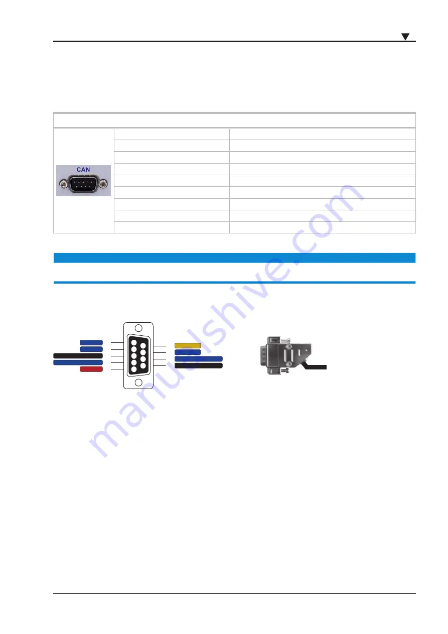
Connection
The measurement is carried out via D-SUB cord.
6
7
8
9
1
2
3
4
5
NC
NC
GNDx CAN (isolated)
CANx low (isolated)
+5 V out
+12 V out
NC
CANx high (isolated)
GND power
Fig. 16: D-SUB-9 CAN connector pin assignment
Highspeed CAN
The highspeed CAN is a differential bus where complementary signals are sent over two wires. The voltage difference
between the two wires defines the logical state of the bus. The differential CAN receiver monitors this voltage differ
-
ence and outputs the bus state with a single-ended output signal.
The highspeed CAN bus topology as well as the possible cable lengths and the recommended termination resistors are
specified in the standards ISO-11898 and CiA 102.
The highspeed CAN bus supports bit rates of up to 1 Mbit/s (or >125 kbit/s).
The schematic below will give you an overview of the highspeed CAN bus topology and the termination resistor place
-
ment.


