


If you have questions or comments, contact us.
Pour toute question ou tout commentaire, nous contacter
.
Si tiene dudas o comentarios, contáctenos.
1-855-558-2422 • www
.dewalt.com
INSTRUCTION MANUAL
GUIDE D’UTILISA
TION
MANUAL DE INSTRUCCIONES
INSTRUCTIVO DE OPERACIÓN, CENTROS DE SER
VICIO Y PÓLIZA
DE GARANTÍA.
ADVER
TENCIA:
LÉASE ESTE INSTRUCTIVO ANTES
DE USAR EL PRODUCTO.
DXMF4618WT
Adjustable W
elding T
able
Table de soudage ajustable
Mesa de soldadura ajustable
Copyright © 2019 D
E
WALT.
D
E
WALT
®
and the D
E
WALT Logo are trademarks of the D
E
WALT Industrial Tool Co., or an affiliate thereof
and are used under license. The yellow/black color scheme is a trademark for D
E
WALT
power tools & accessories.
JS PRODUCTS | 6445 MONTESSOURI STREET, LAS VEGAS, NV 89113
SAVE THESE INSTRUCTIONS
READ ALL INSTRUCTIONS
TECHNICAL SPECIFICATIONS
WARNING! Read and understand all instructions.
This manual contains
important safety and operating instructions.
Please read this manual carefully
before assembling this welding table and save it for reference.
Technical Specifications
Total Capacity
1,000 lb (453.6 kg)
*when weight is evenly distributed
Height
8" - 36" (20.3 cm - 91.4 cm)
Width
46" (116.8 cm)
Depth
18" (45.7 cm)
• Read all instructions thoroughly.
• Remove all components from the box, and lay them on the floor in an orderly fashion.
• Wear eye protection.
• Be cautious of sharp edges.
• Keep this information for further reference.
(DEC 19) Part No. 92796 DXMF4618WT Copyright © 2019, D
E
WALT
ACCESSORIES
1. Remove locking pins
(2)
, grounding stud
(3)
and tool holder
(4)
from the hardware kit. Locate the holes
on either end of the table. You will use both holes during assembly.
2. Remove the nut
(3)
from the grounding stud. From inside the table body, feed the grounding stud
through the designated location (Fig 1). Place the nut and tighten to secure the grounding stud (Fig 2).
3. Remove the nut from the tool holder. From outside the table body, feed the threaded portion of the
tool holder through the designated location (Fig 3). Place the nut and tighten to secure the tool
holder (Fig 4).
Assembly Instructions
GENERAL SAFETY
• Keep work area clean and dry.
• Use correct/recommended tools for the job.
• Never leave unattended tools plugged in or running.
• Wear appropriate safety apparel for the job you are doing.
• Never crawl, sit, stand, or climb on the Welding Table.
• Do not use this Welding Table while working with or around explosives or corrosive liquids.
• Before welding, always inspect the table to be sure it is in good condition.
• Immediately remove work piece from the Welding Table if there is damage, bending, or warping
of the legs or joints.
• Maximum load capacity for the Welding Table is 1000 lb when evenly distributed.
• Maximum point load capacity is 600 lb.
• Before beginning any work, always secure leg locking pins once desired table height is set.
Tools Required for Assembly:
(not included) 4 mm Hex Key or 4 mm Hex Bit, 8 mm Socket
BEFORE YOU BEGIN:
CORD MINDER
1. Locate the leg with two (2) pass-through holes located at the top and bottom of the leg (Fig 5).
2. Pass one (1) M5x57
(11)
bolt through the plastic cord snap, body of the leg and plastic cord minder
(9)
;
making sure the tip of the cord minder attachment is pointing up towards the table top (Fig 6).
3. Apply M5 nylon nut
(13)
and tighten.
4. In the lower hole, pass one (1) M5x50 (10) bolt through the plastic cord snap
(12)
, body of the leg and
plastic cord minder; making sure the tip of the cord minder attachment is pointing down towards
the bottom of the leg (Fig 8).
5. Apply M5 nylon nut and tighten.
6. Once assembled, extension cords can be wrapped around cord minders as well as snapped into
cord snaps for cord management.
IF YOU HAVE ANY QUESTIONS OR COMMENTS ABOUT THIS OR ANY D
E
WALT TOOL,
CALL US TOLL FREE AT:
1-855-558-2422.
HANDLE
1. Following the Operating Instructions in the next section, open the legs and stand the table up.
2. Slide the handle bar
(5)
into the side of the table and through the square receivers underneath the
table top (Fig 8).
3. Insert M6x34
(7)
bolt through the side of the square receiver and apply M6 nylon nut
(8)
and
tighten (Fig 8).
4. Repeat step 3 for the other side of the handle.
5. Insert M5x14
(6)
bolt through the bottom of the square receiver and tighten (Fig 9).
6. Repeat step 5 for the other side of the handle.
- - - -
- -
--
FIG. 1
FIG. 3
FIG. 2
FIG. 4
--
FIG. 6
---
--
--
FIG. 5
- - -
-
--
FIG. 7
--
---
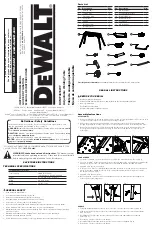
Parts List
No. Description
Qty.
1
Welding Table
1
2
Locking Pins
4
3
Grounding Stud
1
4
Tool Holder
1
5
Handle
1
6
Bolt M5x15mm
2
7
Bolt M6x30mm
2
No. Description
Qty.
8
M6 Nylon Nut
2
9
Cord Minder Brackets
2
10
Bolt M5x50mm
1
11
Bolt M5x57mm
1
12
Cord Snap
2
13
M5 Nylon Nut
2
Definitions: Safety Guidelines
The definitions below describe the level of severity for each signal word. Please
read the manual and pay attention to these symbols.
Indicates a potentially hazardous situation which, if not avoided,
could
result in
death or serious injury.
WARNING:
Indicates a potentially hazardous situation which, if not avoided,
may
result in
minor or moderate injury.
CAUTION:
(Used without word) Indicates a safety related message.
Indicates a practice
not related to personal injury
which, if not avoided,
may
result in
property damage.
NOTICE:
2
5
13
12
7
8
6
3
4
11
10
9
11


