User Manual
Modular Multi-service Integrated Optical Transmission Multiplexer
21
3) Switch on the power of the equipment, the power indicator (PWR) turns
on, which represents the voltage is in order;
4) Optic-fiber connection: Check whether the fiber connector is clean. If
contaminated, apply industrial alcohol to wipe it lightly. When inserting
the fiber jumper, after correctly aligning the fiber connector, lightly screw
the fiber jacket tight (with fiber curvature radius no less than 50mm).
The indicator OPL turns off, which represents the local equipment has
received the optical signal from the opposite end.
Note: Not to stare closely at the inserting holes for optical
elements.
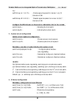
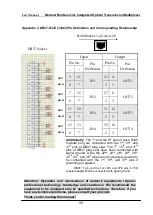
5) Connection of 2M signal line: Switch on all the eight channels of alarm
signals, i.e. dial down the MASK not to mask the E1 channel alarm,
insert IN1-OUT1, IN2-OUT2, IN3-OUT3, IN4-
OUT4…IN8-OUT8 orderly
in IN1, 2, 3, 4…8; When starting up, if the eight indicators E1L1, E1L2,
E1L3, E1L4…E1L8 on the front panel turn out in turn, it means all the
2M channel signals have been entered the optical multiplexer;
6) After completing the above-mentioned procedures, confirm the
equipment working in order, then proceed with the Step 7) (If no NMS
equipment has been ordered or no network monitoring function is
required at the moment, the step shall be ignored);
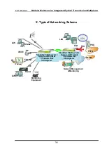
7) Connection of monitoring interface: Select a suitable monitoring
interface according to the network management networking proposal,
and connect the monitoring interface with the NM module. Check the
network connection and carry out NM software commissioning. Till now
the brief installation has been completed. In the case of desktop or
wall-mounted equipment, a clean and stable working environment and
secure installation shall be provided.


