


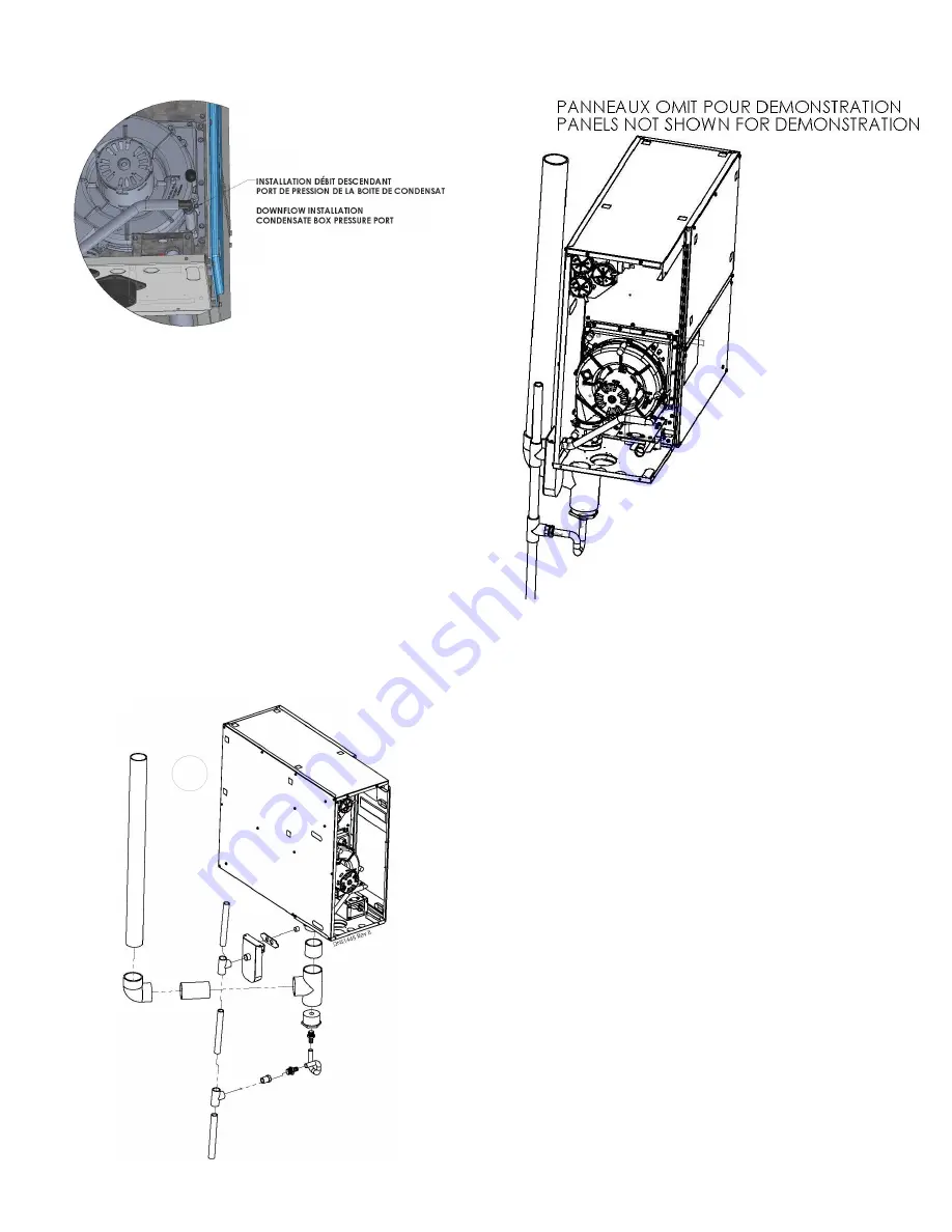
Figure 9 – Downflow condensate box pressure port
Figure 10 – Downflow installation
Figure 11 – Downflow installation detailed
4.3
HORIZONTAL
Horizontal application is perfect for ceiling installation.
Allow enough space for inclination of the furnace and
drain trap.
Figure 12 will help you figure orientiation,
inclination and space needed.
When installing the furnace in horizontal orientation
you must tilt the furnace at least 0.5 in torward the
heat exchanger to ensure proper drainage of the
condensate. See figure 12
4.3.1
Horizontal Condensate drain
connection
1. Remove PVC tubes from the ID blower, condensate
box and vent collector and block the openings with
furnished ½” black caps.
2. Use the furnished extra tubing and cut those 4
lengths : (1) 3.75" , (2) 5.5" , (3) 5.5" and (4) 3.25".
3. Remove the appropriate knock-out for drain trap. It
is on the top of the furnace. Refer to Figure 4, and
look for horizontal drain trap location.
4. Cut open the pressure port, located on the
condensate box behind the inducer.
It will be
connected to the multiposition pressure switch in
section 4.5. For pressure port location see figure
14.
11
Содержание CC15-M-V
Страница 18: ...Figure 17 Wiring Diagram 18...
Страница 23: ...Figure 25 Direct vent clearance 23...
Страница 24: ...Figure 26 Other than Direct vent clearance 24...
Страница 34: ...12 PART LIST Figure 27 Exploded view...
Страница 35: ...Figure 28 Exploded view continued...
Страница 36: ...Table 19 Part list Chinook Compact...
Страница 37: ...Table 20 Part list continued...
Страница 38: ...13 NOTES 38...
Страница 39: ...39...
Страница 40: ...40...