Detcon 880A-N1R Скачать руководство пользователя страница 1


Model 880A-N1R 

Model 880S-N1R 

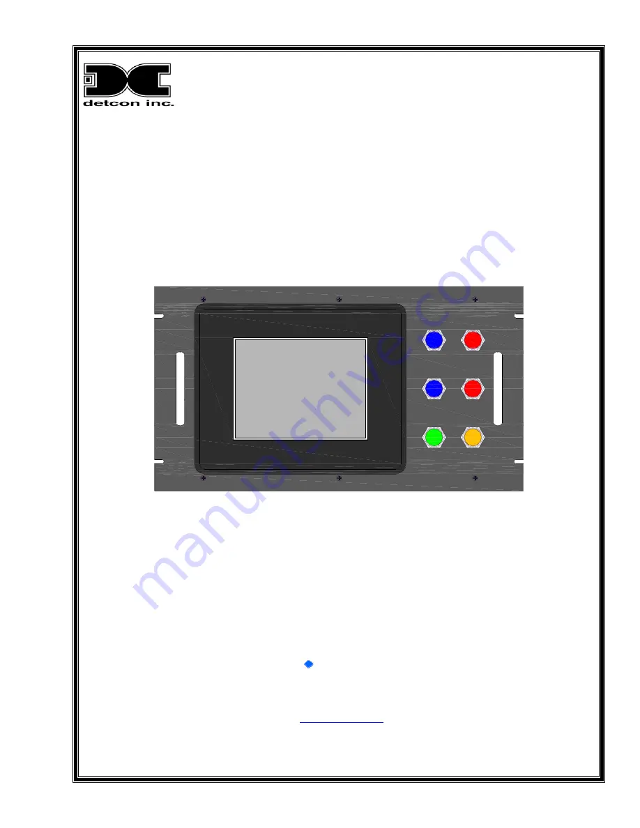
PLC Graphic Control System 


ON / OFF

NO COMM

POWER

ALARM 1

ALARM 3

ALARM 2

FAULT


Operator’s Installation and Instruction Manual 


 DETCON, Inc. 

3200 Research Forest Dr., A-1 

The Woodlands, Texas 77381 

Ph.281.367.4100 / Fax 281.298.2868 

www.detcon.com


May 30, 2009 • Document # 3299 • Revision 0.0 

Содержание 880A-N1R

Страница 1: ...tem ON OFF NO COMM POWER ALARM 1 ALARM 3 ALARM 2 FAULT Operator s Installation and Instruction Manual DETCON Inc 3200 Research Forest Dr A 1 The Woodlands Texas 77381 Ph 281 367 4100 Fax 281 298 2868...

Страница 2: ...880 N1R 880 N1R Instruction Manual ii Page intentionally blank...

Страница 3: ...splay Installation Optional 12 4 0 Setup 15 4 1 User interface 15 4 2 Clock and Screen Adjustments 16 4 3 880 Setup 18 4 4 Remote Display Set up 23 5 0 System Operation 25 5 1 Alarm Indicators 25 5 2...

Страница 4: ...s 17 Figure 26 Clock Adjust Screen 17 Figure 27 Adjust Display Screen 17 Figure 28 Main Screen 18 Figure 29 Analog Configuration Screen 18 Figure 30 Serial Configuration Screen 19 Figure 31 Inputting...

Страница 5: ...erial Systems RS 485 Another method of integration commonly used in industrial applications is the RS 485 serial communications network or Modbus Figure 1 RS 485 serial communication is used for multi...

Страница 6: ...then changes it to Modbus before relaying the information to the 880A The Sensor s output signal is calibrated so that a 4mA input represents a reading of 0 and a 20mA input represents a reading of f...

Страница 7: ...mer annunciator connections 2 1 Configuration A Model 880 is equipped with 8 31 x 6 24 211 2 x 158 4 mm Color Graphical Touch Screen display panel Four slot Programmable Logic Controller PLC o Two com...

Страница 8: ...the programmable Central Processing Unit CPU which processes all instructions data and polls all field devices The CPU utilizes flash memory to store the running program All units are shipped with fir...

Страница 9: ...ocks Room for Customer Supplied Modules PLC Power Supply Network Adapter Power Distribution Terminal Blocks USB Port TOP VIEW Top Removed BACK VIEW TB1 TB2 A B RXD TXD TXD EN CTS C A V C A TX TX RX RX...

Страница 10: ...use of Detcon RL4 Modules Power Input 100 240VAC 50 60Hz 18 30VDC Power Consumption Base Unit 40W Not to include I O Modules and sensors Total Power is dependent on number of I O modules number of sen...

Страница 11: ...but the number of modules that can be mounted should be determined more by the current load imposed on the unit than by the physical space provided The maximum current load is to be restricted to 3Amp...

Страница 12: ...1 set the top switch MSB to 0 and the bottom switch LSB to 1 See Appendix B for Decimal to Hexadecimal conversion NOTE All addresses must be unique There can be no duplication of addresses or a Commun...

Страница 13: ...r Connections 2 For Analog Units 880A Sensor communication is accomplished by using Detcon DA4 modules and the RS 485 Modbus The 4 20mA sensors are directly connected to the DA4 modules while the DA4...

Страница 14: ...y should be connected to the REMOTE OUTPUT terminal blocks and other devices should be connected to the RS 422 SLAVE terminal blocks TXD TXD RXD REMOTE OUTPUT RXD 0V TXD TXD RXD RS 422 SLAVE RXD 0V 11...

Страница 15: ...mplish this turn OFF the 24VDC Input Circuit Breaker located at TB1 5 measure the voltage between TB1 9 and TB1 10 refer to Figure 6 and Figure 10 this reading should be the power supply voltage If th...

Страница 16: ...d be given to prevent sharp objects from colliding with the touch screen The screen can be cleaned with a mild detergent and a lint free cloth Never use an abrasive cleaner on the display 1 Securely m...

Страница 17: ...PUT RXD 0V Figure 18 Remote RS 422 connections 0V RXD REMOTE DISPLAY RXD TXD TXD CUSTOMER SUPPLIED WIRING TXD TXD RXD TERMINAL INPUT RXD 0V TXD TXD RXD REMOTE OUTPUT RXD 0V MAIN 880 Figure 19 Remote I...

Страница 18: ...s Upon completion of all field wiring apply power to the Main 880 and the 880 Remote Display The unit will go through a brief initialization and display the Main Screen Figure 28 The AC box on the dis...

Страница 19: ...e user to input the appropriate numeric response Figure 22 Information entered by the user will be displayed in the box to the left of the keypad Once the user has input the correct information the En...

Страница 20: ...he upper left corner of the touch panel with the wand and holding it there for 3 5 seconds A warning box will appear Figure 23 If no action is taken within 60 seconds the display system will return to...

Страница 21: ...ck Adjust Screen To adjust the Time and Date use the arrow keys Once the correct time and date have been set select OK to close the screen Select Main Menu to exit the Setting screen and select Exit t...

Страница 22: ...ain Screen 2 The display will prompt for a password to enter the 880 System Configuration Screen The default password is 1234 Enter the password in the Pop Up Screen and press enter to continue This w...

Страница 23: ...me can be any alphanumeric string of no more than 40 characters After the facility name has been entered use the ENTER key to transfer the string to the System Configuration Screen Figure 31 Inputting...

Страница 24: ...d by the user before it can become operational a To enable an RL4 module the Bank must be chosen that the RL4 will be associated with and the number of RL4 Modules for that bank must be entered into t...

Страница 25: ...likewise channel number 10 should be addressed as 0Ahex Failure to do so will cause a communication fault to occur and the fault will not clear until the addresses are set properly for all sensors at...

Страница 26: ...mal Place of 1 provides a range of 10 0 10ppm or 10 Likewise a Range entry of 500 with a Decimal Place of 2 provides a range of 5 00 5ppm or 5 11 Select Fault to set the Fault as latching or non latch...

Страница 27: ...lished in much the same manner as the main unit 1 From the Main Screen Figure 28 enter the System Configuration Screen by touching the System Configuration box with the wand 2 The display will prompt...

Страница 28: ...anges of 10 for a unit of 10ppm or 10 will be displayed as 100 likewise entries of 5 for 5ppm or 5 will be displayed as 500 To correctly place the decimal point in the entry select the Decimal Place b...

Страница 29: ...hen the sensor falls below this set point The ALARM 2 LED works independently of the BANK a sensor is assigned to and will illuminate no matter what BANK is in an alarm condition The ALARM 3 LED is il...

Страница 30: ...et as Latching and only after the alarm condition has been cleared Alarm History is a select button that will open the Alarm History Screen Section 5 4 System Configuration is a select button that ope...

Страница 31: ...the Alarm History Screen by using the wand to select the Alarm History button on the Main Screen All alarms that have been cleared or acknowledge may be deleted by selecting the Clear All button on th...

Страница 32: ...A ISOCON Module 3 Once this is done stop the master from communicating but do not power it down This is accomplished on the Model 880 by unplugging the phone jack connection to the FA ISOCON Module 4...

Страница 33: ...n and see if communication is good If so plug in the next slave and check again Repeat this with each slave until all of the slaves are plugged in or one of the slaves takes the data bus down The foll...

Страница 34: ...n part number when ordering spare parts 8 0 Warranty All warranties are FOB the Detcon factory Should any product fail to perform in accordance with published specifications within the warranty period...

Страница 35: ...hus preventing the system from operating properly Since RS 485 allows multiple devices to be connected to the bus wiring is not as straightforward as it is in a bus with only 2 devices The best wiring...

Страница 36: ...s is a very undesirable way to wire an RS 485 bus The chances of problem free operation over the life of the equipment decreases dramatically the further you stray from a straight daisy chain wiring s...

Страница 37: ...ound references is large A solution to this problem is to install an isolated repeater into the data bus to isolate the grounds from each other thus enabling the bus to use only one of the two referen...

Страница 38: ...to check the equipment being installed Some manufacturers include a built in terminating resistor that can be selected by a jumper or dipswitch Detcon Model 880 has such a jumper located on the FA iso...

Страница 39: ...ensor enclosure and be connected to the A B terminals The next segment of cable should also connect to the A B terminals and leave the enclosure headed for the next device The shields must be tied tog...

Страница 40: ...peater 1 device 01 device 02 repeater 2 device 03 and device 05 Notice the termination resistors at the beginning and end of this bus section The second bus starts at repeater 2 It consists of the rep...

Страница 41: ...B D 232 E 8 18 1 2 61 3 D 104 6 8 147 9 3 190 B E 233 E 9 19 1 3 62 3 E 105 6 9 148 9 4 191 B F 234 E A 20 1 4 63 3 F 106 6 A 149 9 5 192 C 0 235 E B 21 1 5 64 4 0 107 6 B 150 9 6 193 C 1 236 E C 22...

Страница 42: ...Forest Dr The Woodlands Texas 77381 Mailing Address P O Box 8067 The Woodlands Texas 77387 8067 Phone 888 367 4286 281 367 4100 Fax 281 292 2860 www detcon com Appendix C Drawings and Diagrams 1 880 N...

Страница 43: ......

Страница 44: ......

Страница 45: ......

Отзывы: