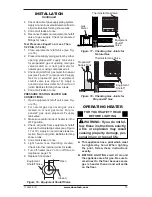
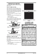
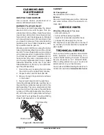
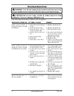
background image

www.desatech.com

119346-01B

6

DETERMINING FRESH-AIR FLOW 
FOR HEATER LOCATION

Determining if You Have a Confined or 
Unconfined Space

Use this work sheet to determine if you have 
a confined or unconfined space.

Space: 

Includes the room in which you will install 

heater plus any adjoining rooms with doorless pas

-

sageways or ventilation grills between the rooms.
1.  Determine the volume of the space (length 

x width x height).


Length x Width x Height =__________cu. ft. 
(volume of space)


Example:

 Space size 20 ft. (6.1 m) (length) x 16 

ft. (4.88 m) (width) x 8 ft. (2.44 m) (ceiling height) 
= 2560 cu. ft. (72.49 m

3

) (volume of space)


If  additional  ventilation  to  adjoining  room 
is supplied with grills or openings, add the 
volume of these rooms to the total volume 
of the space. 

2.  Multiply the space volume by 20 to determine 

the maximum Btu/Hr the space can support.


  ________

(volume of space) x 20 = (Maxi

-

mum Btu/Hr the space can support)


Example:

 2560 cu. ft. (72.49 m

3

) (volume of 

space) x 20 = 51,200 (maximum Btu/Hr the 
space can support)

3.  Add the Btu/Hr of all fuel burning appliances 

in the space.


Vent-free heater 

  __________

Btu/Hr


Gas water heater* 

  __________

Btu/Hr


Gas furnace 

  __________

Btu/Hr


Vented gas heater 

  __________

Btu/Hr


Gas fireplace logs 

  __________

Btu/Hr


Other gas appl __________

Btu/Hr


Total 

=

  _________

Btu/Hr


* Do not include direct-vent gas appliances. 
Direct-vent  draws  combustion  air  from  the 
outdoors and vents to the outdoors.


Example:


Gas water heater 

  __________

Btu/Hr


Vent-free heater 

+

  _________

Btu/Hr


Total 

=

  _________

Btu/Hr

4.  Compare the maximum Btu/Hr the space can 

support with the actual amount of Btu/Hr used.


  _______

Btu/Hr (maximum can support) 


  _______

Btu/Hr (actual amount used)


Example:

  51,200  Btu/Hr  (maximum  the 

space can support)


60,000 Btu/Hr (actual amount of 
Btu/Hr used)

AIR FOR COMbUSTION 

AND VENTILATION

Continued

The space in the above example is a confined 
space because the actual Btu/Hr used is more 
than  the  maximum  Btu/Hr  the  space  can  sup

-

port. You must provide additional fresh air. Your 
options are as follows:
A.  Rework worksheet, adding the space of an 

adjoining room. If the extra space provides 
an unconfined space, remove door to adjoin

-

ing  room  or  add  ventilation  grills  between 
rooms.  See 

Ventilation  Air  From  Inside 

Building.

B.  Vent  room  directly  to  the  outdoors.  See 

Ventilation Air From Outdoors, 

page 7.

C.  Install a lower Btu/Hr heater, if lower Btu/Hr 

size makes room unconfined. 

If the actual Btu/Hr used is less than the maxi

-

mum Btu/Hr the space can support,


the space is 

an unconfined space. You will need no additional 
fresh air ventilation.

 WARNING: If the area in which 

the  heater  may  be  operated  is 

smaller  than  that  defined  as 

an  unconfined  space  or  if  the 

building  is  of  unusually  tight 

construction, provide adequate 

combustion and ventilation air 

by one of the methods described 

in the 

National Fuel Gas Code, 

ANSI Z223.1/NFPA 54 Section 5.3


or applicable local codes.

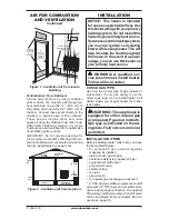
vENTILATION AIR

Ventilation Air From Inside Building

This  fresh  air  would  come  from  an  adjoin

-

ing  unconfined  space.  When  ventilating  to 
an  adjoining  unconfined  space,  you  must 
provide two permanent openings: one within 
12"  (30.5  cm)  of  the  ceiling  and  one  within 
12"  (30.5  cm)  of  the  floor  on  the  wall  con

-

necting the two spaces (see options 1 and 2, 
Figure 2, page 7). You can also remove door 
into adjoining room (see option 3, Figure 2, 
page 7). Follow the 

National Fuel Gas Code, 

ANSI  Z223.1/NFPA  54,  Section  5.3, Air  for 
Combustion and Ventilation

 for required size 

of ventilation grills or ducts.


40,000

  20,000
  60,000

Содержание GWRn18A

Страница 1: ...asoline or other flammable vapors and liquids in the vicinity of this or any other appliance WHAT TO DO IF YOU SMELL GAS Do not try to light any appliance Do not touch any electrical switch do not use any phone in your building Immediatelycallyourgassupplierfromaneighbor s phone Follow the gas supplier s instructions If you cannot reach your gas supplier call the fire department Installation and s...

Страница 2: ...ncer or birth defects or other reproductive harm IMPORTANT Read this owner s manualcarefullyandcompletely before trying to assemble operate or service this heater Improper use of this heater can cause serious injury or death from burns fire explosion electrical shock and carbon monoxide poisoning DANGER Carbonmonoxide poisoning may lead to death Carbon Monoxide Poisoning Early signs of car bon mon...

Страница 3: ... not place propane LP supply tank s inside any structure Locate propane LP supply tank s outdoors 3 This heater shall not be installed in a bedroom or bathroom 4 If you smell gas Shut off gas supply Do not try to light any appliance Do not touch any electrical switch do not use any phone in your building Immediately call your gas supplier from a neighbor s phone Follow the gas supplier s instructi...

Страница 4: ...al gas fired supplemental room heaters shall provide to each purchaser a copy of 527 CMR 30 upon sale of the unit Vent free gas products are prohibited for bedroom and bathroom installation in the Commonwealth of Massachusetts Unpacking 1 Remove heater from carton 2 Remove all protective packaging applied to heater for shipment 3 Check heater for any shipping damage If heater is damaged promptly r...

Страница 5: ...e air that leaks around doors and windows may provide enough fresh air for combustion and ventilation However in buildings of un usually tight construction you must provide additional fresh air Unusually tight construction is defined as construction where a walls and ceilings exposed to the outside atmosphere have a continuous water vapor retarder with a rating of one perm 6 x 10 11 kg per pa sec ...

Страница 6: ...n support ________ Btu Hr actual amount used Example 51 200 Btu Hr maximum the space can support 60 000 Btu Hr actual amount of Btu Hr used AIR FOR COMBUSTION AND VENTILATION Continued The space in the above example is a confined space because the actual Btu Hr used is more than the maximum Btu Hr the space can sup port You must provide additional fresh air Your options are as follows A Rework wor...

Страница 7: ... the event of a power outage you can use this heater as your primary heat source WARNING A qualified ser vice person must install heater Follow all local codes CHECK GAS TYPE Use only the correct type of gas natural or propane LP If your gas supply is not the correct gas type do not install heater Call dealer where you bought heater for proper type heater WARNING This appliance is equipped for eit...

Страница 8: ...nd joining wall You can locate heater on floor away from a wall An optional floor mounting stand is need ed Purchase the floor mounting stand from your dealer See Accessories page 26 WARNING Never install the heater in a bedroom or bathroom in a recreational vehicle where curtains furniture clothing or other flammable objects are less than 36 91 5 cm from the front top or sides of the heater as a ...

Страница 9: ...6 cm Min 16 40 6 cm Min 14 35 6 cm 12 30 4 cm Min Adjoining Wall 14 35 6 cm Adjoining Wall Only Insert Mounting Screws Through Last Hole On Each End Only Insert Mounti Screws Through L Hole On Each En Floor Floor Methods For Attaching Mounting Bracket To Wall Only use last hole on each end of mounting bracket to attach bracket to wall These two holes are 14 35 6 cm apart from their cen ters Attach...

Страница 10: ...Anchor Method For attaching mounting bracket to hollow walls wall areas between studs or solid walls concrete or masonry 1 Drill holes at marked locations using 5 16 drill bit For solid walls concrete or masonry drill at least 1 2 5 cm deep 2 Fold wall anchor as shown in Figure 9 3 Insert wall anchor wings first into hole Tap anchor flush to wall 4 For thin walls 1 2 1 3 cm or less insert red key ...

Страница 11: ...odes Use pipe of large enough diameter to allow proper gas volume to heater If pipe is too small undue loss of volume will occur Typical Inlet Pipe Diameters 16 18 000 Btu hr models 3 8 or greater 26 30 000 Btu hr models 1 2 or greater Installation must include equipment shutoff valve union and plugged 1 8 NPT tap Locate NPT tap within reach for test gauge hook up NPT tap must be upstream from hea...

Страница 12: ...luid toalljoints Bubblesformingshow a leak Correct all leaks at once CAUTION For propane LP gas make sure external regula tor has been installed between propane LP supply and heater See guidelines under Connect ing to Gas Supply page 11 Pressure Testing Gas Supply Piping System Test Pressures In Excess Of 1 2 PSIG 3 5 kPa 1 Disconnect appliance with its appliance main gas valve control valve and e...

Страница 13: ... LP supply tank valve 3 Make sure control knob of heater is in the OFF position 4 Check all joints from equipment shutoff valve to thermostat gas valve see Figure 17 or 18 Apply a noncorrosive leak de tection fluid to all joints Bubbles forming show a leak 5 Correct all leaks at once 6 Light heater see Operating Heater Check all other internal joints for leaks 7 Turn off heater see To Turn Off Gas...

Страница 14: ...o the PI LOT position Keep control knob pressed in for five 5 seconds 7 With control knob pressed in push down and release ignitor button This will light pilot The pilot is attached to the front of burner Note You may be running this heater for the first time after hooking up to gas supply If so you may need to press in control knob for 30 seconds or more This will allow air to bleed from the gas ...

Страница 15: ...urner Only pilot stays lit Turn control knob clockwise to the PILOT position THERMOSTAT Control OPERATION The thermostatic control used on these models differs from standard thermostats Standard thermostats simply turn on and off the burner The thermostat used on this heater senses the room temperature At times the room may exceed the set temperature If so the burner will shut off The burner will ...

Страница 16: ... Figure 27 shows an incorrect burner flame pattern If burner flame pattern is incorrect as shown in Figure 27 turn heater off see To Turn Off Gas to Ap pliance page 15 see Troubleshooting page 18 Thermocouple Pilot Burner Pilot Burner Thermocouple Blue Flame Yellow Flame Figure 24 Correct Pilot Flame Pattern Figure 25 Incorrect Pilot Flame Pattern Figure 26 Correct Burner Flame Pattern Figure 27 I...

Страница 17: ...es a clean burning flame Keep these holes clear of dust dirt and lint Clean these air inlet holes prior to each heating season Blocked air holes will create soot We recommend that you clean the unit every three months during operation and have heater inspected yearly by a qualified service person We also recommend that you keep the burner tube and pilot assembly clean and free of dust and dirt To ...

Страница 18: ...or setting is not correct 1 Not enough combustion ventilation air REMEDY 1 Replace pilot assembly 2 Replace pilot assembly 3 Reconnect ignitor cable 4 Free ignitor cable if pinched by any metal or tubing Keep ignitor cable dry 5 Replace ignitor cable 6 Replace ignitor 7 Tighten nut holding piezo ignitor Nut is located inside heater cabinet at top 1 Turn on gas supply or open equipment shutoff valv...

Страница 19: ...valve 4 Hand tighten until snug then tighten 1 4 turn more 5 A Contact local natural or propane LP gas company B Clean ODS pilot see Cleaning and Maintenance page 16 or replace ODS pilot assembly 6 Replace pilot assembly 7 Replace control valve 8 Wait one minute for safety interlock system to reset Repeat ignition operation 1 Clean burner orifice s see Cleaning and Maintenance page 16 or replace b...

Страница 20: ...ate and correct all leaks see Checking Gas Con nections page 12 2 Replace control valve 1 Take apart gas tubing and remove foreign matter 2 Locate and correct all leaks see Checking Gas Con nections page 12 1 Operate burner until air is removed from line Have gas line checked by local natural or propane LP gas company 2 Observe minimum installa tion clearances see Figure 4 page 8 3 Clean burner se...

Страница 21: ...er Weight 29 lb 13 2 kg Average Shipping Weight 33 lb 15 kg GWRP16A and GWRP16TA Propane LP Gas 16 000 Btu hr GWRP16 is variable Piezo Ignition Pressure Regulator Setting 8 W C Inlet Gas Pressure in of water Maximum 14 Minimum 11 Average Heater Weight 22 lb 10 kg Average Shipping Weight 25 5 lb 11 6 kg GWRP26A and GWRP26TA Propane LP Gas 26 000 Btu hr GWRP26 is variable Piezo Ignition Pressure Reg...

Страница 22: ...esatech com 119346 01B 22 Illustrated Parts Breakdown Cabinet body Models GWRP16A GWRn18A GWRP26A GWRN30A GWRP16TA GWRn18TA GWRP26TA and GWRn30TA 14 15 8 5 6 7 4 3 1 2 16 10 9 11 12 13 17 See pages 24 and 25 ...

Страница 23: ...5 01 Roll Pin 1 11 098354 03 Control Knob 1 12 099415 18 Gas Regulator Propane LP Gas 1 099415 19 Gas Regulator Natural Gas 1 13 104819 02 Regulator Bracket 1 14 098522 24 Thermostat Gas Valve 1 15 102394 02 Thermostat Valve Mounting Bracket 1 16 107660 01 Inlet Tube 1 107660 03 Inlet Tube 1 103256 02 Inlet Tube 1 17 118721 04 Baffle 1 118721 03 Baffle 1 PARTS AVAILABLE NOT SHOWN 100642 03 Hardwar...

Страница 24: ...er Nut 1 7 099056 24 Injector Plaque A or C 1 2 099056 25 Injector Plaque A or C 1 2 8 099056 01 Injector Plaque B 1 099056 02 Injector Plaque B 1 9 103844 01 Control Valve 1 100747 01 Control Valve 1 10 103352 03 Tubing Valve to Plaque 1 103353 04 Tubing Valve to Plaque 1 11 103352 04 Tubing Valve to Plaque 1 103353 05 Tubing Valve to Plaque 1 12 103353 06 Tubing Valve to Plaque 1 If replacing OD...

Страница 25: ...njector Plaque B 1 099056 02 Injector Plaque B 1 If replacing ODS pilot and your model is pre 2002 your part number will be 099059 07 for natural gas models 103894 04 for propane LP models The thermocouple part number will be 098514 01 for both gases The electrode part number will be 098594 01 for both gases Burner Assembly GWRP26TA and GWRN30TA ILLUSTRATED PARTS BREAKDOWN and PARTS LIST Burner As...

Страница 26: ...placement Parts Note Use only original replacement parts This will protect your warranty coverage for parts replaced under warranty Parts Under Warranty Contact authorized dealers of this product If they can t supply original replacement part s call DESA Heating Products Technical Ser vice Department at 1 866 672 6040 When calling DESA Heating Products have ready your name your address model and s...

Страница 27: ... dealers of this product and or DESA Heating Products who will provide original factory replacement parts Failure to use original factory replacement parts voids this warranty The heater MUST be installed by a qualified installer in accordance with all local codes and instructions furnished with the unit This warranty does not apply to parts that are not in original condition because of normal wea...

Отзывы: