background image

www.deltamachinery.com

(800) 223-7278 - US

(800) 463-3582 - CANADA

10" Contractors Saw

(Model 36-978/36-979)

$ELTA,OGO
0-3BLACK

7HITELOGOWITHBLACK
BACKGROUNDISTHEPRIMARY
USEOFOURTRADEMARK7HEN
SIZEOFLOGOFALLSBELOW
ORTHEREISNOBLACKBACKGROUND
THENUSETHEBOTTOMLOGO

4HISVERSIONOFTHETRADEMARKIS
ONLYTOBEUSEDWHENTHEPRODUCT
ISPRESENT

Lijadora de Correa 

de 1 pulg. / Disco 

de 8 pulg.

Ponceuse à 

courroie de 

25,4 mm (1 po) à 

disque de 203 mm 

(8 po)

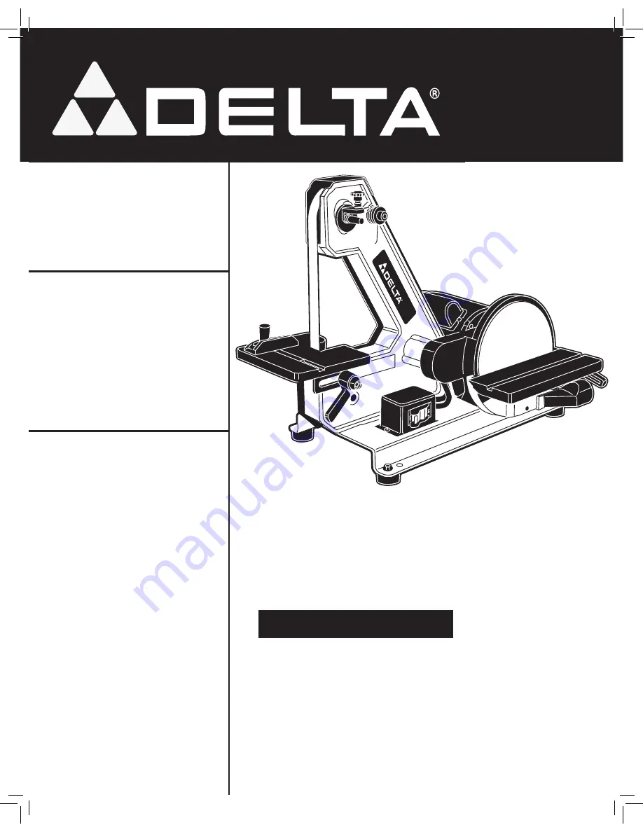
1" Belt / 8" Disc 

Sander


Instruction  Manual

Manuel d’Utilisation

Manual de Instrucciones

SA180

FRANÇAIS 21  

ESPAÑOL 41


A15105 - 01-13-06  Rev. A

Copyright © 2006 Delta Machinery

Содержание SA180

Страница 1: ...BELOW OR THERE IS NO BLACK BACKGROUND THEN USE THE BOTTOM LOGO 4HIS VERSION OF THE TRADEMARK IS ONLY TO BE USED WHEN THE PRODUCT IS PRESENT Lijadora de Correa de 1 pulg Disco de 8 pulg Ponceuse à courroie de 25 4 mm 1 po à disque de 203 mm 8 po 1 Belt 8 Disc Sander Instruction Manual Manuel d Utilisation Manual de Instrucciones SA180 FRANÇAIS 21 ESPAÑOL 41 A15105 01 13 06 Rev A Copyright 2006 Delt...

Страница 2: ...y strongly recommends that this product NOT be modified and or used for any application other than for which it was designed If you have any questions relative to its application DO NOT use the product until you have written Delta Machinery and we have advised you Online contact form at www deltamachinery com Postal Mail Technical Service Manager Delta Machinery 4825 Highway 45 North Jackson TN 38...

Страница 3: ...zardous situation which if not avoided may result in property damage safety guidelines definitions Some dust created by power sanding sawing grinding drilling and other construction activities contains chemicals known to cause cancer birth defects or other reproductive harm Some examples of these chemicals are lead from lead based paints crystalline silica from bricks and cement and other masonry ...

Страница 4: ...damage to the machine or injury to the user 14 USE THE PROPER EXTENSION CORD Make sure your extension cord is in good condition When using an extension cord be sure to use one heavy enough to carry the current your product will draw An undersized cord will cause a drop in line voltage resulting in loss of power and overheating See the Extension Cord Chart for the correct size depending on the cord...

Страница 5: ...the space between the abrasive disc and the table 13 SUPPORT THE WORKPIECE firmly with a miter gauge backstop or work table when sanding with a belt Hold the workpiece firmly Loss of control of the workpiece can result in injury 14 AVOID KICKBACK by sanding in accordance with the directional arrows Feed the workpiece against the downward rotation side of the disc or the forward rotation of the bel...

Страница 6: ... electrician Improper connection of the equipment grounding conduc tor can result in risk of electric shock The conductor with insulation having an outer surface that is green with or without yellow stripes is the equipment grounding conductor If repair or replacement of the electric cord or plug is necessary do not connect the equipment grounding conductor to a live terminal Check with a qualifie...

Страница 7: ... to 25 18 AWG 0 6 120 25 50 16 AWG 0 6 120 50 100 16 AWG 0 6 120 100 150 14 AWG 6 10 120 up to 25 18 AWG 6 10 120 25 50 16 AWG 6 10 120 50 100 14 AWG 6 10 120 100 150 12 AWG 10 12 120 up to 25 16 AWG 10 12 120 25 50 16 AWG 10 12 120 50 100 14 AWG 10 12 120 100 150 12 AWG 12 16 120 up to 25 14 AWG 12 16 120 25 50 12 AWG 12 16 120 greater than 50 feet not recommended FOREWORD Delta Model SA180 is th...

Страница 8: ... 10mm Flat Washer 4 6 10mm Lockwasher 2 7 3 16 Flat Washer 2 8 6 4mm Internal Tooth Lockwasher 1 9 M4x 07 Wing Nut 1 1 2 3 4 5 6 7 8 9 1 2 3 4 5 6 7 8 9 10 11 12 13 14 CARTON CONTENTS UNPACKING AND CLEANING Carefully unpack the machine and all loose items from the shipping container s Remove the rust preventative oil from unpainted surfaces using a soft cloth moistened with mineral spirits paint t...

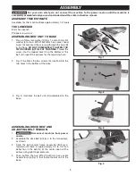
Страница 9: ...e belt and adjusting belt tension 1 Disconnect machine from power source 2 Assemble the drive belt A Fig 4 to the two pulleys as shown 3 Slide the belt sander frame assembly B Fig 4 forward until there is approximately 1 4 to 1 2 inch de flec tion in the belt A at the center span of the pulleys using light finger pressure 4 Then tighten the two M10x1 5x20mm hex socket head screws A Fig 2 that fast...

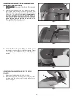
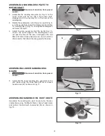
Страница 10: ...ly tighten screws B and C at this time as the guard must be adjusted to sanding disc plate NOTE Access to screw C is through hole D in top of guard 3 Assemble the inside guard E Fig 6 to the guard assembly using a M4x 07x45mm cheese head screw F Fig 7 and M4x 07 wing nut G Fig 6 as shown assembling sanding disc to disc plate 1 Make sure the disc plate A Fig 8 is clean 2 Peel backing from sanding d...

Страница 11: ...the disc guard so that the lip G Fig 10 covers the outer edge of the sanding disc but not past the face of the disc and tighten the two M4x 07x10mm cheese head screws one of which is shown at H that attach the disc guard to the base assembling lower sanding disc guard 1 Disconnect machine from power source 2 Assemble the lower sanding disc guard A to the disc base using the three M4x 07x10mm chees...

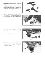
Страница 12: ...disc base casting making sure the key F on the table bracket is engaged with the keyway G on the base casting 4 Place a 10mm flat washer J Fig 15 onto locking stud H Fig 15 and thread stud into base casting to hold table assembly E in place as shown 5 Place handle C Fig 15 onto locking stud H and fasten with screw A and spring B 6 Fig 16 illustrates the locking handle C assembled NOTE The locking ...

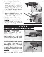
Страница 13: ...ig 22 A B E D operation STARTING AND STOPPING SANDER Make sure that the switch is in the OFF position before plugging cord into outlet Do not touch the plug s metal prongs when unplugging or plugging in the cord The on off switch A Fig 21 is located on the front of the sander To turn the machine ON move the switch up to the ON position To turn the machine OFF move the switch A down to the OFF posi...

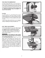
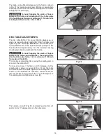
Страница 14: ...able A Fig 25 can be tilted or moved in or out by loosening lock handle B moving the table to the desired position and tightening lock handle B NOTE The lock handle B is spring loaded and can be re po si tioned by pulling out on the handle and repositioning it on the serrated locking stud located directly under the handle To avoid trapping the work or fingers between the table and sanding belt the...

Страница 15: ...ing out the handle B and repositioning it on the serrated locking stud located directly underneath the handle To avoid trapping the work or fingers between the table and sanding disc the sanding disc C should be adjusted so it is a maximum of 1 16 inch from edge of table D This can be ac com plished by moving the sanding disc in or out on the motor shaft To check and see if the table is at 90 degr...

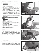
Страница 16: ...d installing abrasive discs 1 Disconnect machine from power source 2 Remove the sanding disc table 3 Remove the old abrasive disc by peeling it from the sanding disc plate 4 Clean the disc plate thoroughly 5 Remove the backing from the new abrasive disc and press the abrasive disc firmly onto the disc plate 6 Replace the sanding disc table miter gage A miter gage A Fig 33 is supplied with your san...

Страница 17: ... the disc unit with or without the table tilted and using the miter gage as a guide NOTE Always sand on the left downward side of the sanding disc as shown Sand ing on the right upward side of the sanding disc could cause the workpiece to fly up which could be hazardous Sanding outside curves on the belt unit with the platen Sharpening a wood chisel on the belt unit using a block of wood to suppor...

Страница 18: ...ig 40 Fig 41 Polishing using the Delta accessory Felt Belt in place of the sanding belt Sanding in tight areas with the sanding belt Inside curves can be sanded on the top sanding wheel with the side cover removed ...

Страница 19: ...r FAILURE TO START Should your machine fail to start check to make sure the prongs on the cord plug are making good contact in the outlet Also check for blown fuses or open circuit breakers in the line LUBRICATION RUST PROTECTION Apply household floor paste wax to the machine table extension table or other work surface weekly Or use a commercially available protective product designed for this pur...

Страница 20: ...of of purchase of the product within two years and provides Delta with reasonable opportunity to verify the alleged defect by inspection For all refurbished Delta product the warranty period is 180 days Delta may require that electric motors be returned prepaid to a motor manufacturer s authorized station for inspection and repair or replacement Delta will not be responsible for any asserted defec...

Страница 21: ...21 FRANÇAIS ...

Страница 22: ...n importe quelles questions relatives à son application n utilisent pas le produit jusqu à ce que vous avez écrit Delta Machinery et nous vous avons conseillé La forme en ligne de contact à www deltamachinery com Courrier Postal Technical Service Manager Delta Machinery 4825 Highway 45 North Jackson TN 38305 Information en ce qui concerne l opération sûre et correcte de cet outil est disponible de...

Страница 23: ...olongateur est en bon état Lorsqu un cordon prolongateur est utilisé s assurer que celui ci est d un calibre suffisant pour l alimentation nécessaire à la machine Un cordon d un calibre insuffisant entraînera une perte de tension d où une perte de puissance et surchauffe Voir le tableau sur les cordons prolongateurs pour obtenir le calibre approprié selon la longueur du cordon et l ampérage de la ...

Страница 24: ...e abrasif La pièce pourrait être entraînée dans l espace entre le disque abrasif et la table 13 SUPPORTER LA PIÈCE fermement avec le guide à onglet un butoir ou une table de travail en cas de ponçage avec une courroie Tenir la pièce fermement Perdre le contrôle de la pièce pourrait causer un accident 14 ÉVITER L EFFET DE REBOND en ponçant conformément aux flèches directionnelles Alimenter la pièce...

Страница 25: ...place par une vis en métal REMARQUE Au Canada le Code canadien de l électriciténe permet pas l emploi d un adaptateur temporaire Dans tous les cas s assurer quela prise en question est bien mise à la terre Dans le doute demander à un électricien compétent de vérifier la prise 1 Toutes les machines avec cordon mis à la terre Dans l éventualité d un mauvais fonctionnement ou d unepanne la mise à la ...

Страница 26: ...6 10 120 25 50 16 AWG 6 10 120 50 100 14 AWG 6 10 120 100 150 12 AWG 10 12 120 up to 25 16 AWG 10 12 120 25 50 16 AWG 10 12 120 50 100 14 AWG 10 12 120 100 150 12 AWG 12 16 120 up to 25 14 AWG 12 16 120 25 50 12 AWG 12 16 120 50 PI PLUS GRANDS QUE NON RECOMMANDES DESCRIPTION FONCTIONNELLE AVANT PROPOS Le modèle Delta SA180 est le nec le plus ultra pour le ponçage du bois et le meulage du métal La ...

Страница 27: ...s à tête cylindrique bombée M6 x 1 x 15 mm 3 1 vis à tête cylindrique bombée M4 x 0 07 x 45 mm 4 5 vis à tête cylindrique bombée M4 x 0 07 x 10 mm 5 4 rondelles plates de 10 mm 6 2 rondelles de blocage de 10 mm 7 2 rondelles plates de 4 8 mm 3 16 po 8 1 rondelle à denture intérieure de 6 4 mm 9 1 écrou à oreilles M4 x 0 07 Fig 1A Pièces de la ponceuse 1 Assemblage de la courroie 2 Moteur courroie ...

Страница 28: ... VIS A FIG 2 Visser la vis dans le trou taraudé C dans la partie inférieure de la ponceuse à courroie Répéter le procédé pour l autre trou 2 La fig 2 illustre les deux vis A insérées dans les deux trous de la partie inférieure de la base 3 La fig 3 illustre la ponceuse à courroie D assemblée à la base ASSEMBLAGE DE LA COURROIE D ENTRAÎNEMENT ET RÉGLAGE DE LA TENSION 1 débrancher l appareil de la s...

Страница 29: ... SERA NÉCESSAIRE DE RÉGLER LE DISPOSITIF DE PROTECTION À LA PLAQUE DE SUPPORT D ABRASIF REMARQUE l accès à la vis C s effectue par le trou D sur le dessus du dispositif de protection 3 Assembler le dispositif de protection interne E fig 6 au module de protection à l aide d une vis à tête cylindrique bombée de M4 x 0 07 x 45 mm F fig 7 et un écrou à oreilles de M4 x 0 07 G fig 6 comme indiqué ASSEM...

Страница 30: ... que la lèvre G fig 10 couvre le bord externe du disque abrasif puis serrer les deux vis à tête cylindrique bombée M4 x 0 07 x 10 mm dont une est illustré en H qui retiennent le dispositif à la base ASSEMBLAGE DU DISPOSITIF INFÉRIEUR DE PROTECTION POUR LE DISQUE 1 débrancher l appareil de la source d alimentation 2 Assembler le dispositif inférieur de protection A de la ponceuse à bande abrasive à...

Страница 31: ... fig 14 sur la base moulée de la ponceuse à disque S assurer que la clé F du support de table soit engagée G dans la base moulée 4 Enfiler une rondelle plate de 10 mm J fig 15 sur le goujon de verrouillage H fig 15 et visser le goujon dans la base moulée pour fixer le module de la table E en position comme indiqué 5 Installer la poignée C fig 15 sur le goujon de verrouillage H et la fixer avec la ...

Страница 32: ...ur se trouve sur la position d arrêt avant de brancher le cordon d alimentation dans la prise Ne pas toucher aux lames métalliques de la fiche lors du branchement ou débranchement du cordon L interrupteur marche arrêt on off A fig 21 est situé à l avant de la ponceuse Pour mettre la ponceuse sous tension déplacer l interrupteur vers le haut en position de marche Pour l éteindre déplacer l interrup...

Страница 33: ...onceuse à bande abrasive A fig 25 s incline ou se déplacer vers l intérieur ou l extérieur en desserrant la poignée de blocage B Déplacer la table à la position souhaitée puis serrer la poignée de blocage B REMARQUE la poignée de blocage B est à ressort et se déplace en retirant la poignée et en la repositionnant sur le goujon à crans d arrêt situé directement sous la poignée pour éviter de coince...

Страница 34: ...errouillage B REMARQUE la poignée de blocage B est à ressort et se déplace en retirant la poignée B et en la repositionnant sur le goujon à crans d arrêt situé directement sous la poignée pour éviter de coincer la pièce ou les doigts entre la table et le disque abrasif positionner le disque abrasif C à un maximum de 1 6 mm 1 16 po du bord de la table D Déplacer le disque abrasif vers l intérieur o...

Страница 35: ...LATION DES DISQUES ABRASIFS 1 débrancher l appareil de la source d alimentation 2 Retirer la table de la ponceuse à disque 3 Décoller le vieux disque abrasif de la plaque support d abrasif 4 Nettoyer soigneusement la plaque support 5 Décoller la pellicule au dos du nouveau disque abrasif et l appliquer fermement sur la plaque 6 Remplacer la table de la ponceuse à disque JAUGE À ONGLET Une jauge à ...

Страница 36: ...nçage d aluminium à l aide de la ponceuse à disque avec la table à niveau et la jauge à onglets servant de guide REMARQUE toujours poncer sur le côté gauche vers le bas du disque abrasif comme indiqué Un ponçage sur le côté droit vers le haut du disque abrasif risque de projeter la pièce dans les airs ce qui s avèrerait dangereux Ponçage de courbes externes sur la ponceuse à courroie à l aide de l...

Страница 37: ...Polissage à l aide de la bande feutrée Delta à la place de la bande abrasive Ponçage dans des espaces restreints à l aide de la bande abrasive Utiliser la roue supérieure pour poncer les courbes internessans le panneau latéral ...

Страница 38: ... machine ne démarre pas s assurer que les lames de la fiche du cordon d alimentation sont bien enfoncées dans la prise de courant Vérifier également que les fusibles ne sont pas grillés ou que le disjoncteur ne s est pas déclenché LUBRIFICATION ET PROTECTION CONTRE LA ROUILLE Appliquer chaque semaine une cire à parquets d usage domestique sur la table de la machine sur la rallonge de table ou tout...

Страница 39: ...ne succursale d usine ou composer le 1 800 223 7278 pour le service à la clientèle et recevoir ainsi une assistance personnalisée de techniciens bien formés ENTRETIEN ET RÉPARATION Tous les outils de qualité finissent par demander un entretien ou un changement de pièce Pour de plus amples renseignements à propos de Delta Machinery ses succursales d usine ou un centre de réparation sous SERVICE gar...

Страница 40: ...e des produits Delta réusinés est de 180 jours Delta peut demander que les moteurs électriques soient retournés transport payé d avance à un centre de réparation autorisé du fabricant du moteur en vue d une inspection d une réparation ou d un remplacement Delta ne peut être tenu pour responsable des défauts résultants de l usure normale de la mauvaise utilisation de l abus de la réparation ou de l...

Страница 41: ...41 ESPAÑOL ...
Страница 42: ...ARDE ESTAS INSTRUCCIONES indica una situación de inminente riesgo la cual si no es evitada causará la muerte o lesiones serias indica una situación potencialmente riesgosa que si no es evitada podría resultar en la muerte o lesiones serias indica una situación potencialmente peligrosa la cual si no es evitada podría resultar en lesiones menores o mode radas usado sin el símbolo de seguridad de ale...

Страница 43: ...s condiciones Cuando utilice un cordón de extensión asegúrese de utilizar un cordón que sea lo suficientemente pesado como para llevar la corriente que su producto tome Un cordón de tamaño insuficiente causará una caída de la tensión de la línea lo cual producirá una pérdida de potencia y recalentamiento Consulte el Cuadro de cordones de extensión para obtener el tamaño correcto dependiendo de la ...

Страница 44: ... una correa Sujete firmemente la pieza de trabajo Una pérdida de control de la pieza de trabajo es peligrosa 14 EVITE EL RETROCESO lijando de acuerdo con las flechas direccionales Haga avanzar la pieza de trabajo contra el lado de rotación hacia abajo del disco o contra el sentido de rotación hacia delante de la correa Una pérdida de control de la pieza de trabajo es peligrosa 14 EVITE EL RETROCES...

Страница 45: ...nchufe a un receptáculo coincidente de dos conductores tal como se muestra en la Fig B si no se dispone de un tomacorriente conectado a tierra apropiadamente El adaptador temporal debe utilizarse solamente hasta que un electricista calificado pueda instalar un tomacorriente conectado a tierra apropiadamente La orejeta lengüeta etc rígida de color verde que sobresale del adaptador debe conectarse a...

Страница 46: ...MÁQUINAS ELÉCTRICAS ESTACIONARIAS Capacidad Nominal En Amperios Voltios Longitud Total Del Cordon En Pies Calibre Del Cordon De Extensión 0 6 120 Hasta 25 18 AWG 0 6 120 25 50 16 AWG 0 6 120 50 100 16 AWG 0 6 120 100 150 14 AWG 6 10 120 Hasta 25 18 AWG 6 10 120 25 50 16 AWG 6 10 120 50 100 14 AWG 6 10 120 100 150 12 AWG 10 12 120 Hasta 25 16 AWG 10 12 120 25 50 16 AWG 10 12 120 50 100 14 AWG 10 12...

Страница 47: ... Tête De Fromage De M4x 07x10mm 5 5 Arandela Plana De 10mm 4 6 Arandela De Cierre 10mm 2 7 Arandela Plana Del 3 16 2 8 Frein d écrou Interne De Dent De 6 4mm 1 9 Tuerca De Ala M4x 07 1 CONTENIDO DE CARTON Desembale cuidadosamente la máquina y todos los elementos sueltos del o los contenedores de envío Retire el aceite anticorrosivo de las superficies sin pintura con un paño suave humedecido con al...

Страница 48: ... Ensamble la correa de marcha A Fig 4 a las dos poleas como se ilustra aquí 3 Deslice el conjunto del marco de la lijadora B Fig 4 hacia adelante hasta que exista en la correa A una deflexión de aproximadamente 1 4 a 1 2 pulgada en el tramo central entre las poleas utilizando presión ligera con los dedos 4 Apriete entonces los dos tornillos que afianzan la ENSAMBLAJE Para su propia seguridad no co...

Страница 49: ...protector No apriete los tornillos B y C completamente en este momento ya que el protector debe ser ajustado al plato del disco de lijado 3 Ensamble el protector interior E Fig 6 al conjunto del protector con el tornillo F Fig 7 y la tuerca de mariposa G Fig 6 como se ilustra aquí ENSAMBLAJE DEL DISCO DE LIJADO AL PLATO DEL DISCO 1 Asegúrese que el plato del disco A Fig 8 esté limpio 2 Quite el re...

Страница 50: ...juste el protector del disco de manera que el borde G Fig 10 cubra la orilla exterior del disco de lijado y apriete los dos tornillos de los cuales aparece uno en H que conectan el protector del disco a la base ENSAMBLAJE DEL PROTECTOR INFERIOR DEL DISCO DE LIJADO 1 Disconecte la máquina de fuente de engería 2 Ensamble el protector inferior del disco de lijado A a la base del disco utilizando los ...

Страница 51: ...granada con la chaveta G en la estructura de la base 4 Utilizando el gorrón de cierre H Fig 15 del conjunto de la agarradera y la arandela plana J enrosque el gorrón de cierre H en el agujero roscado de la estructura de la base para sostener el conjunto de la mesa E en su sitio como se ilustra aquí 5 Ensamble la agarradera C Fig 15 al gorrón de cierre H y afiáncela con un tornillo A y el resorte B...

Страница 52: ... D OPERACIÓN ARRANCANDO Y DETENIENDO LA LIJADORA Asegúrese de que el interruptor esté en la posición de APAGADO OFF antes de enchufar el cable de alimentación en el tomacorriente No toque las patas de metal del enchufe al enchufar o desenchufar el cable El interruptor de ENCENDIDO APAGADO A Fig 21 está localizadosobre una caja de interruptores en la base de la lijadora Para ENCENDER la máquina mue...

Страница 53: ...vida hacia adentro o afuera mediante el aflojado de la agarradera de cierre B moviendo la mesa a la posición deseada y apretando nuevamente la agarradera de cierre B AVISO La agarradera de cierre B está accionada por resorte y puede ser colocada en distintas maneras tomando la agarradera y colocándola sobre el gorrón de cierre dentado localizado debajo de la agarradera Para evitar atrapar el mater...

Страница 54: ...en distintas maneras tomando la agarradera B y colocándola sobre el gorrón de cierre dentado localizado debajo de la agarradera Para evitar atrapar el material o los dedos entre la mesa y el disco de Lijado el disco de lijado C debe colocarse a un maximo de 1 16 de pulgada del borde de la mesa D Esto puede conseguirse al mover el disco de lijado hacia adentro o afuera en el eje del motor Para veri...

Страница 55: ...te la mesa del disco de lijado 3 Quite el viejo disco abrasante del plato del disco de lijado 4 Limpie el plato del disco concienzudamente 5 Quite el respaldo de la parte trasera del nuevo disco abrasante y oprima el disco abrasante firmemente sobre el plato del disco 6 Vuelva a colocar la mesa del disco de lijado ESCUADRA DE INGLETES Se suministra una escuadra de ingletes A Fig 33 junto con su li...

Страница 56: ...iempre del lado izquierdo hacia abajo del disco de lijado como se ilustra aquí El lijado en el lado derecho hacia arriba del disco puede hacer que el mater ial vuele hacia arriba lo que puede ser peligroso Lijando curvas exteriores sobre la unidad de correa con el plato fuera de sitio Afilando un cincel de madera sobre la unidad de correa haciendo uso de un bloque de madera para apoyar el cincel y...

Страница 57: ...orrea de lijado AVISO La mayoría de las operaciones de pulido se realizan con el plato fuera de su sitio Lijado en espacios apretados con la correa de lijado Las curvas interiores pueden ser lijadas sobre la rueda de lijado superior con la tapa lateral fuera de su sitio Fig 39 Fig 40 Fig 41 ...

Страница 58: ...e semanalmente cera en pasta para pisos a la mesa de la máquina y a la extensión u otra superficie de trabajo También puede usar productos protectores disponibles en comercios y diseñados con este propósito Siga las instruc ciones del fabricante para su uso y seguridad Para limpiar el óxido de las mesas de hierro fundido necesitará los siguientes materiales 1 hoja de Almohadilla Manual para Matiza...

Страница 59: ...tro de atención al cliente al 1 800 223 7278 para obtener asistencia personalizada de nuestros técnicos capacitados MANTENIMIENTO Y REPARACIONES Con el paso del tiempo todas las herramientas de calidad requieren mantenimiento o reemplazo de las piezas Para obtener información acerca de Delta Machinery sus sucursales propias o un Centro de mantenimiento con garantía autorizado visite nuestro sitio ...

Страница 60: ... Jackson TN 38305 www deltamachinery com GARANTIA Para registrar la herramienta para obtener el mantenimiento cubierto por la garantía de la herramienta visite nuestro sitio web en www deltamachinery com Garantía limitada de dos años para productos nuevos Delta reparará o reemplazará a expensas y opción propias cualquier máquina nueva pieza de máquina nueva o accesorio de máquina nuevo Delta que d...

Отзывы: