background image

D V P - E S 3   S e r i e s   O p e r a t i o n   Ma n u a l  

6 - 2 4  

_6 

6.6


Testing and Debugging a Program


6.6.1


Creating a Connection


Before you download a program and parameters to a PLC or monitor them online, connect ISPSoft to the PLC. 

In this example, connect ISPSoft to the CPU module DVP32ES311T with a USB cable. Refer to Section 2.4 in 

the ISPSoft User Manual for more information about connecting ISPSoft to a PLC in other ways. Refer to the 

AS Operation Manual for more information about wiring. 

You can skip this section if you have connected ISPSoft to a PLC successfully as described in Section 

2.4 in the ISPSoft User Manual. 

(1)  Make sure that the wiring is correct, and then power on the CPU module. 

(2)  Connect the CPU module to the computer with a USB cable. If the USB driver for the DVP-ES3 series 

CPU module is installed on the computer, 

Delta PLC

 appears in the 

Device Manager

 window, and a port 

number is assigned to 

Delta PLC

. Refer to Appendix A for more information about installing a USB driver. 

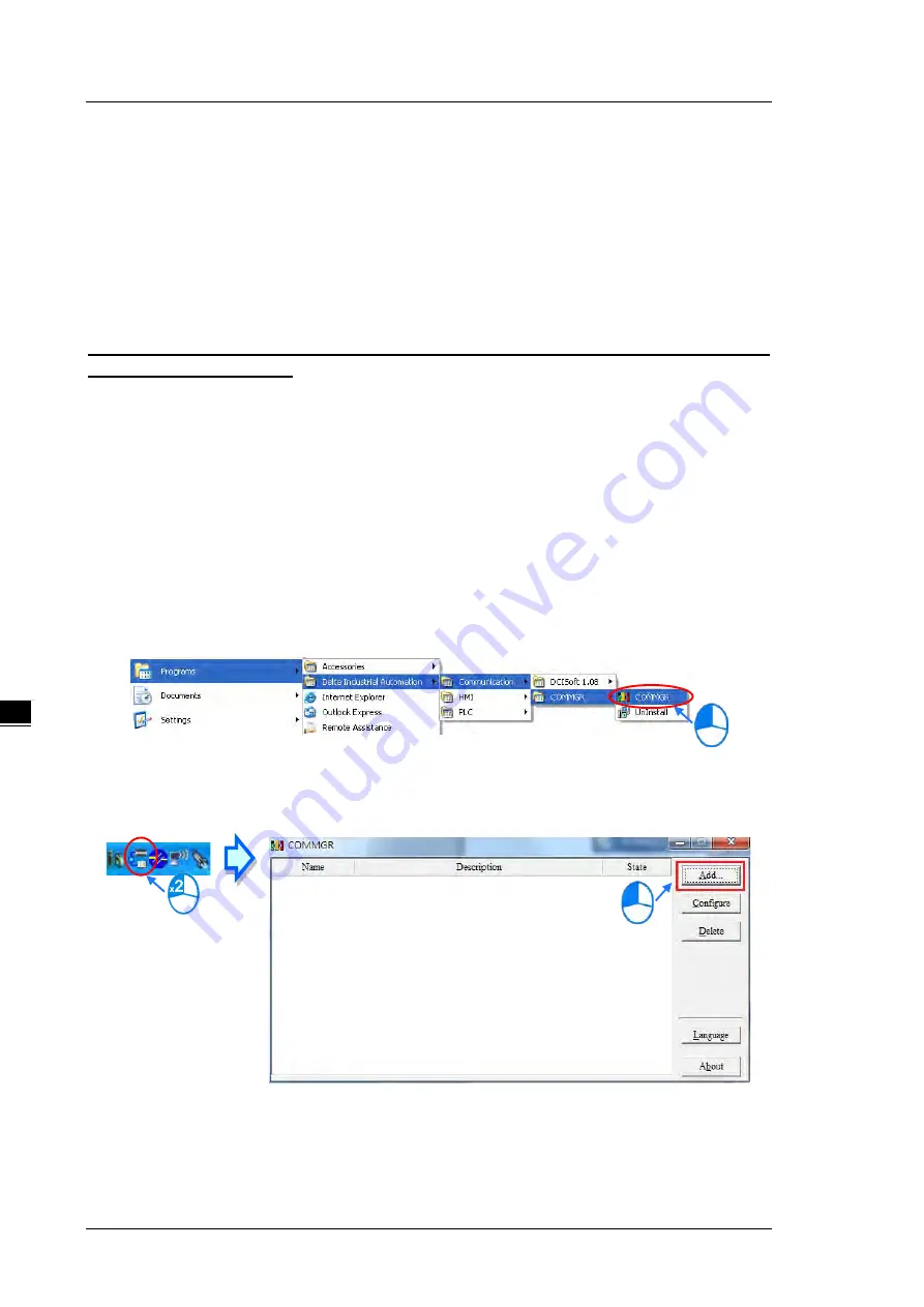
(3)  Make sure that COMMGR is started and the icon representing COMMGR is displayed on the system tray. 

If the icon representing COMMGR is not displayed on the system tray, start COMMGR by clicking the 

shortcut on the 

Start

 menu (

Start 

Programs 

Delta Industrial Automation 

Communication 

COMMGR)


(4)  Double-click the icon representing COMMGR on the system tray to open the 

COMMGR

 window. Click 

Add


in the 

COMMGR

 window to create a driver. 


Содержание DVP-ES3 Series

Страница 1: ... reserve the right to change the information in this manual without prior notice EMEA Headquarters Delta Electronics Netherlands B V Sales Sales IA EMEA deltaww com Marketing Marketing IA EMEA deltaww com Technical Support iatechnicalsupport deltaww com Customer Support Customer Support deltaww com Service Service IA emea deltaww com TEL 31 0 40 800 3800 BENELUX Delta Electronics Netherlands B V D...

Страница 2: ...DVP ES3 Series Operation Manual Revision History Version Revision Date 1s t The first version was published 2019 09 05 ...

Страница 3: ... Digital Input Output Module Profiles 2 12 2 3 3 Digital Input Output Module Terminals 2 13 2 3 4 Digital Input Output Module Terminals 2 13 2 4 Analog Input Output Module Specifications 2 16 2 4 1 General Specifications 2 16 2 4 2 Analog Input Output Module Profiles 2 20 2 4 3 Analog Input Output Terminals 2 21 2 4 4 Analog Input Output Module Terminals 2 21 2 5 Temperature Measurement Modules Sp...

Страница 4: ...1 Linking the CPU module and a module 4 6 4 3 2 Installation on the Set 4 7 4 4 Wiring 4 8 4 5 Connecting Power Cables 4 10 4 5 1 Precautions 4 10 4 5 2 Ground 4 10 4 5 3 Wiring Power Supply 4 11 4 5 4 Power Consumption 4 12 4 6 Wiring CPU Modules 4 14 4 6 1 Wiring Digital Input Terminals 4 14 4 6 2 Wiring Digital Output Terminals 4 17 4 6 3 Wiring RS 485 Terminals 4 21 4 6 4 Wiring CANopen Termin...

Страница 5: ...uction to CPU Devices 5 2 5 1 1 Device Table 5 2 5 1 2 Basic Structure of I O Storage 5 3 5 1 3 Relation Between the PLC Action and the Device Type 5 3 5 1 4 Latched Areas in the Device Range 5 4 5 2 CPU Device Functions 5 5 5 2 1 Values and Constants 5 5 5 2 2 Floating point Numbers 5 7 5 2 2 1 Single precision Floating point Numbers 5 7 5 2 2 2 Decimal Floating point Numbers 5 8 5 2 3 Strings 5 ...

Страница 6: ...asic Editing Creating a Contact and a Coil 6 9 6 5 3 Basic Editing Inserting a Network and Typing an Instruction 6 12 6 5 4 Basic Editing Selection of a Network and Operation 6 14 6 5 5 Basic Editing Connecting a Contact in Parallel 6 17 6 5 6 Basic Editing Editing a Comment 6 18 6 5 7 Basic Editing Inserting an Applied Instruction 6 19 6 5 8 Basic Editing Creating a Comparison Contact and Typing ...

Страница 7: ...Log 7 18 Chapter 8 Hardware Configuration and Data Exchange Setups 8 1 Hardware Configuration Tool for DVP ES3 Series Modules 8 2 8 1 1 Introduction of the HWCONFIG Environment 8 2 8 1 2 Configuring a Module 8 3 8 1 3 Editing a Comment 8 3 8 2 Setting the Parameters in a DVP ES3 Series CPU Module 8 4 8 2 1 Opening the PLC Parameter Setting Window 8 4 8 2 2 Setting the Basic CPU Parameters 8 5 8 3 ...

Страница 8: ... 1 IP Address Types 9 15 9 4 2 2 Set the IP Address Static IP 9 15 9 4 2 3 Set the IP Address BOOTP DHCP 9 17 9 4 2 4 Re enable BOOTP DHCP 9 20 9 5 Troubleshooting 9 22 9 5 1 Error Code Classification 9 22 9 5 2 Error Codes How to fix them 9 22 9 5 2 1 Configuration Errors 9 22 9 5 2 2 Application Error 9 25 9 6 Studio 5000 Software Operation 9 26 9 6 1 Architecture 9 26 9 6 2 Create a New Project...

Страница 9: ...r Class ID 356 Hex 9 62 9 7 17 HC Register Class ID 357 Hex 9 63 9 7 18 SM Register Class ID 358 Hex 9 64 9 7 19 SR Register Class ID 359 Hex 9 64 9 8 Delta EIP Product List 9 65 9 8 1 Delta EIP Products 9 65 9 8 2 Delta EIP Products DLR Device Level Ring supported 9 66 9 8 3 Delta EIP Products Scanner supported 9 66 9 9 Operation and Monitor on the Web 9 67 9 9 1 Getting Started 9 67 9 9 1 1 Expl...

Страница 10: ... SDO NMT and Reading Emergency Message through the Ladder Diagram 10 19 10 4 1 Data Structure of SDO Request Message 10 19 10 4 2 Data Structure of NMT Message 10 21 10 4 3 Data Structure of EMERGENCY Request Message 10 23 10 4 4 Example of Sending SDO through the Ladder Diagram 10 25 10 5 Troubleshooting 10 27 10 5 1 CANopen Network Node State Display 10 27 10 6 Application Example 10 30 10 7 Obj...

Страница 11: ...rrors Without LED Indicators 12 6 12 3 Troubleshooting for Analog Modules AD DA XA and Temperature Modules PT TC 12 13 12 4 LED Indicators and Error Codes for CPU Modules 12 14 Chapter 13 Data Tracer and Data Logger 13 1 Data Tracer 13 2 13 1 1 About Data Tracer 13 2 13 1 2 Example 13 4 13 2 Data Logger 13 5 13 2 1 About Data Logger 13 5 13 2 2 Related SM Flags and SR Registors 13 7 Appendix A Ins...

Страница 12: ... 4 C1 3 Cables C 5 Appendix D Maintenance and Inspection D 1 Cautions D 2 D 2 Daily Maintenance D 3 D 2 1 Required Inspection Tools D 3 D 2 2 Daily Inspection D 3 D 3 Periodic Maintenance D 4 D 3 1 Required Inspection Tools D 4 D 3 2 Periodic Inspection D 5 ...

Страница 13: ...1 1 Chapter 1 Product Introduction Table of Contents 1 1 Overview 1 2 1 1 1 Related Manuals 1 2 1 1 2 Models Descriptions 1 2 1 2 Overview 1 7 1 3 Characteristics 1 8 1 ...

Страница 14: ...oduces electrical specifications dimensions CPU functions devices module tables troubleshooting and so forth 1 1 2 Models Descriptions Classification Model Name Description DVP ES3 Series CPU module DVP32ES311T 24 VDC powered CPU module NPN output 1x Ethernet port 2x RS 485 ports 1x USB port 1x Micro SD interface supporting 32 I Os 16DI 16DO and up to 256 I Os Program capacity 64K steps removable ...

Страница 15: ... capacity 64K steps removable terminal blocks DVP64ES300R 100 220 VAC powered CPU module Relay output 1x Ethernet port 2x RS 485 ports 1x USB port 1x Micro SD interface supporting 64 I Os 32DI 32DO and up to 256 I Os Program capacity 64K steps removable terminal blocks DVP80ES300T 100 220 VAC powered CPU module NPN output 1x Ethernet port 2x RS 485 ports 1x USB port 1x Micro SD interface supportin...

Страница 16: ...C 5mA 4 NPN sinking outputs 5 30VDC 0 5A output 4A COM DVP08XN211R 8 Relay outputs 250VAC Below 30VDC 2A output 5A COM DVP08XN211T 8 NPN sinking outputs 5 30VDC 0 5A output 4A COM DVP16XM211N 16 inputs 24VDC 5mA DVP16XP211R 8 inputs 24VDC 5mA 8 Relay outputs 250VAC Below 30VDC 2A output 5A COM DVP16XP211T 8 inputs 24VDC 5mA 8 NPN sinking outputs 5 30VDC ...

Страница 17: ...inking outputs 5 30VDC 0 5A output 4A COM DVP24XP200R 16 inputs 24VDC 5mA 8 Relay outputs 250VAC Below 30VDC 2A output 5A COM DVP24XP200T 16 inputs 24VDC 5mA 8 NPN sinking outputs 5 30VDC 0 5A output 4A COM DVP24XN200R 24 Relay outputs 250VAC Below 30VDC 2A output 5A COM DVP24XN200T 24 NPN sinking outputs 5 30VDC 0 5A output 4A COM DVP32XP200R 16 inputs 24VDC 5mA 8 Relay outputs ...

Страница 18: ...solution 14 bits 10V 10V 20mA 20mA Conversion time 400 μs channel DVP04DA E2 4 channel analog input module Hardware resolution 14 bits 10V 10V 20mA 20mA Conversion time 400 μs channel DVP06XA E2 4 channel analog input Hardware resolution 14 bits 5V 5V 10V 10V 20mA 20mA Hardware resolution 13 bits 0 4 20mA Conversion time 400 μs channel 2 channel analog output Hardware resolution 14 bits 10V 10V 20...

Страница 19: ...puts It provides a strong network function for users and users can create connection among devices on the network through software An DVP ES3 Series CPU module also provides structured programming Users can assign programs to different tasks and write a program which is frequently executed in a function block Besides users can choose different programming languages ladder diagrams LD structured te...

Страница 20: ...ut at 200 kHz 2 Supporting more inputs and outputs The DVP ES3 Series CPU module supports up to 256 digital I Os inputs outputs or 8 analog I O modules 3 Larger program capacity and memory The AS300 Series advanced CPU modules have 64k steps of program capacity 60000 general registers 30000 for specific use and 30000 for programming editing and 64k words of memory that can be used for storing para...

Страница 21: ...eed to send the signal to the corresponding input of the function block You do not need to consider the processing procedure inside the function block A function block is a program element equipped with the operation function It is similar to a subroutine and is a type of POU Program Organization Unit It cannot operate by itself and must be called through the main program POU The function defined ...

Страница 22: ...RS 485 serial control interfaces COM1 and COM2 which can be set as a either master or slave Built in CAN communication port is for Delta Special Driver and CANopen DS301 communication mode 9 High speed Ethernet communication interface DVP ES3 Series CPU modules are equipped with a 10 100 M Ethernet communication interface and support email web Modbust TCP Ethernet IP Adapter and socket services 10...

Страница 23: ...hese programming languages For the DVP ES3 Series PLC structured text ST does not support debugging mode and sequential function charts SFC supports debugging mode during the action and the transition Step 1 Set the PLC to RUN Step 2 Entering the on line mode Step 2 Enter online mode ...

Страница 24: ...ebugging mode 12 On line editing mode You can use the on line editing mode when the system is running to update the program without affecting the system operation When the system is in the on line monitoring mode enter the on line editing mode by clicking ...

Страница 25: ...Chapter 1 Product Introduction 1 13 1_ After the program is modified and compiled you can update the program in the CPU module by clicking to download it to the CPU ...

Страница 26: ...DVP ES3 Series Operation Manual 1 14 _1 MEMO ...

Страница 27: ...nput Output Module Terminals 2 13 2 4 Analog Input Output Module Specifications 2 16 2 4 1 General Specifications 2 16 2 4 2 Analog Input Output Module Profiles 2 20 2 4 3 Analog Input Output Terminals 2 21 2 4 4 Analog Input Output Module Terminals 2 21 2 5 Temperature Measurement Modules Specifications 2 22 2 5 1 General Specifications 2 22 2 5 2 Temperature Measurement Module Profiles 2 24 2 5 ...

Страница 28: ...d with 5 Hz f 8 4 Hz constant amplitude 3 5 mm 8 4 Hz f 150 Hz constant acceleration 1g Duration of oscillation 10 sweep cycles per axis on each direction of the three mutually perpendicular axes International Standard IEC 61131 2 IEC 60068 2 6 TEST Fc Shock resistance Tested with Half sine wave Strength of shock 15 g peak value 11 ms duration Shock direction The shocks in each in direction per ax...

Страница 29: ...llation DIN rails or screws Installation of a module No backplane installation only module after module Maximum number of modules which can be installed Up to 8 modules for AIO modules and cannot exceed 256 IO points Number of tasks 283 tasks 32 cyclic tasks 16 I O interrupts four timed interrupts etc Refer to ISPSoft Manual for more information Number of inputs outputs 256 Number of inputs output...

Страница 30: ...m DVP32ES311T Supply voltage 24 VDC 20 4 VDC 28 8 VDC 15 to 20 Weight g 390 g Electrical specifications for the inputs on digital input output module The signals passing through the inputs are 24 VDC signals Model Item DVP32ES311T DVP32ES300T DVP32ES300R DVP48ES300T DVP48ES300R DVP64ES300T DVP64ES300R DVP80ES300T DVP80ES300R Number of inputs 16 X0 X17 24 X0 X27 32 X0 X37 40 X0 X47 Connector type R...

Страница 31: ... 24 32 40 16 16 24 32 40 Connector type Removable terminal blocks Output form Relay Transistor T sinking Voltage 10 250 VAC 5 30VDC 5 30VDC Leakage current 0uA 10uA Maximum load Resistance 2A output 5A COM 0 5A output 2A COM 2 Inductance Life cycle curve 3 12W 24VDC Bulb 20WDC 100WAC 2W 24VDC Switching frequency 1 1Hz Y0 Y7 200kHz Y10 Y47 1kHz Maximum Response time OFF ON Approximately 10ms Y0 Y7 ...

Страница 32: ...there is an input signal the input LED indicator is ON If there is an output signal the output LED indicator is ON 3 Power LED Indicates the power status of the CPU module Run LED Operating status of the module ON the program is running OFF the program is stopped Blinking the program detects an error Error LED Error status of the module Blinking slowly 1 second ON 3 seconds OFF warning Blinking 0 ...

Страница 33: ...GND Y 15 Y1 7 Y16 26 27 28 DVP32ES300T X2 X1 X0 S S 24 G 2 4V X5 X4 X3 Y4 Y3 Y2 Y 1 Y 0 D Y 7 Y6 Y5 D D D DVP32ES300T 16DI 16DO X15 X1 4 X 12 X11 X10 X7 X 6 Y1 0 X16 Y11 Y13 Y12 Y14 X13 SG 1 2 3 4 5 6 7 8 9 10 11 12 13 14 16 15 17 18 19 20 21 22 23 1 2 3 4 5 6 7 8 9 10 11 12 1 3 14 16 15 17 18 19 20 21 22 2 3 24 2 5 L N X 17 24 CAN CAN GND Y 15 Y1 7 Y16 26 27 28 U P0 ZP 0 U P1 ZP1 DVP32ES311T X2 X...

Страница 34: ...2 Y1 Y0 D Y5 Y4 D D D DVP64ES300T 32DI 32DO X4 X2 X1 X0 S S0 X7 X6 X5 X17 X16 X14 X13 X12 X11 X10 Y7 Y6 Y12 Y11 Y10 X34 X33 X31 X30 Y20 Y22 Y21 Y23 Y25 Y24 X3 X15 X32 SG Y13 1 2 3 4 5 6 7 8 9 10 11 12 13 14 16 15 17 18 19 20 21 22 1 2 3 4 5 6 7 8 9 10 11 12 13 14 16 15 17 18 19 20 21 22 25 26 27 28 29 30 31 32 33 44 45 46 47 48 30 31 32 33 34 35 36 37 23 24 24 G 24 V L N 23 24 CA N CA N GN D Y26 3...

Страница 35: ... X43 S G Y12 1 2 3 4 5 6 7 8 9 10 11 12 13 14 16 15 17 18 19 20 2 1 22 23 24 25 31 3 2 3 3 34 35 37 38 39 40 41 4 2 1 2 3 4 5 6 7 8 9 1 0 11 12 13 14 16 15 17 18 1 9 20 21 22 2 3 24 25 28 2 9 30 3 1 32 33 34 35 37 38 39 40 41 42 43 44 45 4 6 36 X4 5 X44 X46 X47 Y2 1 Y20 Y 22 Y23 28 29 30 X27 X26 X2 4 X 23 X25 36 Y 31 Y30 Y3 3 Y32 Y35 Y34 Y37 Y 36 Y41 Y40 Y43 Y42 Y45 Y44 43 44 45 4 6 4 7 48 49 50 5...

Страница 36: ...e Digital input Input form Direct current sinking or sourcing Input voltage 24VDC 5mA Action level OFF ON 15VDC ON OFF 5VDC Response time OFF ON 10ms 10 ON OFF 15ms 10 Input impedance 4 7kΩ Input signal Voltage input Sinking The inputs are NPN transistors whose collectors are open collectors Sourcing The inputs are PNP transistors whose collectors are open collectors Electrical isolation Optocoupl...

Страница 37: ...cle affects the frequency 2 UP ZP should include external aid power 24VDC 15 20 and the rated comsumption is around 1mA point 3 DVP16XN211R and DVP16XP211R should include external aid power 24VDC 15 20 and the rated comsumption is around 5mA point 4 The life cycle curve is shown below Contact Current A 20 0 5 0 1 0 2 30 50 0 3 0 7 1 2 200 300 500 100 1000 2000 3000 Operation X10 3 120VAC Resistive...

Страница 38: ...ures the module on the set 5 Model name Model name of the module 6 Power LED Indicates the power status of the CPU module 7 Input output LED indicator If there is an input signal the input LED indicator is ON If there is an output signal the output LED indicator is ON 8 External module connection port Connects the modules 9 DIN rail slot 35 mm For the DIN rail 10 I O module securing clip Secures t...

Страница 39: ...6XM2 11N 16XP2 11R T 16XN2 11R T 24XP2 00R T 24XN2 00R T 32XP2 00R T Refer to L 45 70 145 L1 37 62 137 2 3 4 Digital Input Output Module Terminals DVP08XM211N NC X3 X2 X1 NC X7 X6 X5 X0 X4 NC DVP08XM2 8DI S S 1 2 3 4 5 6 1 2 3 4 5 6 DVP08XN211R T NC Y3 Y2 Y1 NC Y7 Y6 Y5 Y0 Y4 C1 DVP08XN2 R 8DO C0 1 2 3 4 5 6 1 2 3 4 5 6 Y3 Y2 Y1 Y0 Y7 Y6 Y5 Y4 NC ZP UP DVP08XN2 T 8DO NC 1 2 3 4 5 6 1 2 3 4 5 6 ...

Страница 40: ...7 8 9 10 DVP16XN211R T C1 Y3 Y2 Y1 Y11 Y10 C2 Y0 0V 24V DVP16XN2 R 16DO C0 Y7 Y6 Y5 Y4 Y17 Y16 Y15 Y14 Y13 Y12 1 2 3 4 5 6 7 8 9 10 11 12 1 2 3 4 5 6 7 8 9 10 Y3 Y2 Y1 Y0 Y13 Y12 Y11 ZP0 ZP1 UP1 DVP16XN2 T 16DO UP0 Y7 Y6 Y5 Y4 NC Y17 Y16 Y15 Y14 Y10 1 2 3 4 5 6 7 8 9 10 1 2 3 4 5 6 7 8 9 10 11 12 DVP16XP211R T X4 X3 X2 X1 Y1 Y0 C0 X0 0V 24V DVP16XP2 R 8DI 8DO S S NC X7 X6 X5 Y7 Y6 Y5 Y4 Y3 Y2 1 2 ...

Страница 41: ...3 Y2 Y1 ZP0 24G 24V DVP24XN2 T 24DO UP0 NC Y7 Y6 Y5 Y22 Y21 Y20 ZP2 UP2 NC Y23 NC N L Y0 Y14 Y13 Y12 Y11 ZP1 UP1 Y17 Y16 Y15 Y26 Y25 Y24 ZP3 UP3 NC Y27 NC Y10 1 2 3 4 5 6 7 8 9 10 11 12 13 14 15 16 17 18 19 20 21 1 2 3 4 5 6 7 8 9 10 20 21 1 2 3 4 5 6 7 8 9 10 11 12 13 14 15 16 17 18 19 20 21 1 2 3 4 5 6 7 8 9 10 20 21 DVP32XP200R T X5 X4 X3 X2 X0 24G 24V DVP32XP2 R 16DI 16DO S S X10 X7 X6 X15 X14...

Страница 42: ...0 mA 0 20 mA 4 20 mA Digital conversion range 32 000 32 000 32 000 0 32 000 0 32 000 Hardware input limit 1 10 12V 5 06V 20 24 mA 0 24 20 24 mA 3 81 20 19 mA Digital conversion limit 2 32 384 32 384 32 384 384 32 384 384 32 384 Hardware resolution 14 bit 14 bit 14 bit 13 bit 13 bit Input impedance 1M Ω 250 Ω Absolute input range 3 15 V 32 mA Digital data format 16 bit two s complement number Avera...

Страница 43: ...istance to the terminal is 5 mm Conversion time 400 μs channel Short cicuit protection 1 Yes Weight 194 g 207 g 1 The module is with short circuit protection but if the duration of a short circuit is too long it can cause circuit damage Current output can be open circuit Things to note when connecting the module to a CPU PLC module 1 Up to 8 modules can be connected to a CPU PLC module 2 The conne...

Страница 44: ...n connecting the module to a CPU PLC module 1 Up to 8 modules can be connected to a CPU PLC module 2 The connected module is numbered automatically from 0 nearest to the CPU PLC module to 7 furthest away from the CPU PLC module 3 The connected modules do NOT take up any digital I O points A D Functional specifications Voltage input Current input Analog input channel 4 channels Rated input range 10...

Страница 45: ...f an input signal exceeds the absolute range it might damage the channel D A Functional specifications Voltage output Current output Analog output channel 2 channels Rated output range 10V 10V 0 20 mA 4 mA 20 mA Digital conversion range 32 000 32 000 0 32 000 0 32 000 Digital conversion limit 32 768 32 767 0 32 767 6 400 32 767 Hardware resolution 14 bit 14 bit 14 bit Maximum output current 5 mA L...

Страница 46: ...he module 5 POWER LED indicator Indicates the status of the power supply ON the power is on OFF no power ERROR LED indicator Error status of the module ON a serious error occurs in the module OFF the module is normal Blinking a minor error occurs in the module Analog to digital conversion indicator Indicates the analog to digital conversion status Blinking conversion is taking place OFF stop conve...

Страница 47: ... FE VI2 1 2 3 4 5 6 7 8 9 10 11 12 1 2 3 4 5 6 7 8 DVP02DA E2 FE FE FE 0V 24V DVP02DA E2 2AO AG IO2 VO2 AG IO1 VO1 1 2 3 4 5 6 7 8 9 10 11 12 DVP04DA E2 1 2 3 4 5 6 7 8 9 10 11 12 IO4 VO4 FE 0V 24V DVP04DA E2 4AO FE AG IO2 VO2 FE AG IO1 VO1 FE AG IO3 VO3 FE AG 1 2 3 4 5 6 7 8 DVP06XA E2 FE FE FE 0V 24V DVP06XA E2 4AI 2AO IO1 VO1 VI2 I2 V2 VI1 I1 V1 VI4 I4 V4 VI3 I3 V3 AG IO2 VO2 AG 1 2 3 4 5 6 7 8...

Страница 48: ...Applicable sensor 04PT 3 Wire Pt100 DIN 43760 1980 JIS C1604 1989 100Ω 3850 PPM C Pt1000 DIN EN60751 1 kΩ 3850 PPM C Ni100 Ni1000 DIN 43760 input impedence 0 300Ω 0 3000Ω 06PT 3 Wire Pt100 DIN 43760 1980 JIS C1604 1989 100Ω 3850 PPM C Pt1000 DIN EN60751 1 kΩ 3850 PPM C Ni100 Ni1000 DIN 43760 Cu50 Cu100 JPt100 JIS C1604 1989 LG Ni1000 input impedence 0 300Ω 0 3000Ω Rated input range Pt100 180 C to ...

Страница 49: ...s can be connected to a CPU PLC module 2 The connected module is numbered automatically from 0 nearest to the CPU PLC module to 7 furthest away from the CPU PLC module 3 The connected modules do NOT take up any digital I O points Functional specifications Centigrade C Fahrenheit F Input impedance Analog input channel Four Digital data format 16 bit two s complement number Overall accuracy 25 C 77 ...

Страница 50: ...annels are isolated from one another by optocouplers Isolation between a digital circuit and a ground 500 VDC Isolation between an analog circuit and a ground 500 VDC Isolation between an analog circuit and a digital circuit 500 VDC Isolation between the 24 VDC and a ground 500 VDC Isolation between analog channels 120 VAC 2 5 2 Temperature Measurement Module Profiles 1 4 5 3 6 7 8 2 9 0 4PT E2 4A...

Страница 51: ...le Analog to digital conversion indicator Indicates the analog to digital conversion status Blinking conversion is taking place OFF stop conversion 6 External module connection port Connects the modules 7 DIN rail slot 35 mm For the DIN rail 8 I O module securing clip Secures the modules 9 Mounting hole Secures the module on the set 2 5 3 Temperature Measurement Module Dimensions 70 62 106 98 78 9...

Страница 52: ...2 F E I1 I 1 O1 FE I3 I3 O 3 FE I2 1 2 3 4 5 6 7 8 9 10 11 12 1 2 3 4 5 6 7 8 DVP06PT E2 I5 O5 FE 0V 24V DVP06PT E2 6A I I5 I2 O2 I1 I 1 O1 FE I3 I3 O3 F E I2 1 2 3 4 5 6 7 8 9 10 11 12 1 2 3 4 5 6 7 8 9 10 11 12 I6 O6 I6 I 4 I4 O4 DVP04TC E2 FE FE FE 0V 24V DVP04TC E2 4AI FE FE FE I2 I2 FE I1 I1 FE I4 I4 FE I3 I3 1 2 3 4 5 6 7 8 9 10 11 12 1 2 3 4 5 6 7 8 ...

Страница 53: ...tension modules and the installation does not count as any digital extension point or analog module Model Item DVPAEXT01 E2 DVPAEXT1R E2 DVPAEXT1L E2 Weight 50 g 55 g 2 6 2 Extension Cable Interface Module Profiles DVPAEXT1R E2 right side previous one DVPAEXT1L E2 left side latter one 78 90 23 1 1 3 2 4 90 96 78 27 4 3 2 1 1 Number Name Description 1 I O module securing clip Secures the modules 2 ...

Страница 54: ...ince the installation space is limited you can use DVPAEXT01 E2 DVPAEXT1R E2 DVPAEXT1L E2 to extend the communication signal and the connection between DVP ES2 EX2 series CPU and the DI DO or AI AO extension modules D VPAE XT1L E2 D VPAEXT1R E2 Pin Definition Use the enclosed cable to connect DVPAEXT1R E2 and DVPAEXT1L E2 1 2 3 4 5 6 7 8 9 1 2 3 4 5 6 7 8 9 ...

Страница 55: ...ware Table of Contents 3 1 Installing and Uninstalling ISPSoft 3 2 3 1 1 Installing ISPSoft 3 3 3 1 2 Uninstalling ISPSoft 3 7 3 2 Installing and Uninstalling COMMGR 3 9 3 2 1 Installing COMMGR 3 9 3 2 2 Uninstalling COMMGR 3 12 3 ...

Страница 56: ... general keyboard mouse or devices compatible with Windows Printer A printer with a driver for Windows This is needed to print projects RS 232 port For connecting to a PLC One of them is used but a PLC that is connected must have a corresponding port 1 USB port For connecting to a PLC Ethernet port For connecting to a PLC Communication software COMMGR a communication manager must be installed 2 Su...

Страница 57: ...stallation program from the official Delta website http www deltaww com to download ISPSoft The installation programs need to be decompressed if downloaded from the internet 3 Click Start and Run to open the Run window Specify the path denoting the executable file which is used to install COMMGR in the Open box and then click OK Alternatively you can double click the ISPSoft setup icon to execute ...

Страница 58: ...al 3 4 _3 6 Type related information in the User Name box and the Organization box and then click Next 7 Choose I accept the terms in the license agreement Click Next to proceed to the next step 8 Then click Next for the next step ...

Страница 59: ...Chapter 3 Installing Software 3 5 3_ 9 Check the installation information and then click Install ...

Страница 60: ...tion Manual 3 6 _3 10 After installation is complete click Finish to continue the next step 11 When installation is complete shortcuts to the software is created on the desktop and Start menu Click Close to exit the setup ...

Страница 61: ...tall is not found there are two methods to uninstall the software Method 1 Choose ISPSoft x xx from the Windows list click More then select Open file location Method 2 Place ProgramData Microsoft Windows Start Menu Programs Delta Industrial Automation PLC in the address box and press Enter Then double click ISPSoft x xx file 2 Remove the software by double clicking the ISPSoft UnInstall ...

Страница 62: ...DVP ES3 Series Operation Manual 3 8 _3 3 To uninstall ISPSoft click Yes shown in the pop up window The window will automatically close once the software is removed ...

Страница 63: ...ng system You have to log in to the system as a system administrator before installing COMMGR 2 Put a COMMGR CD in the CD ROM drive or download the installation program from the official Delta website http www deltaww com The installation programs need to be decompressed if downloaded from the internet 3 Click Start and then click Run to open the Run window Specify the path denoting the executable...

Страница 64: ... Manual 3 10 _3 4 When the previous version of COMMGR is installed click OK to remove that version shown in the pop up window see below and when uninstall is complete click OK again 5 Click Next after the Setup window appears ...

Страница 65: ...Software 3 11 3_ 6 Use default setup in the destination folder Click Install to start the installation 7 When the installation is complete the shortcut for COMMGR is created on the Start menu click Finish to close the setup ...

Страница 66: ...S3 Series Operation Manual 3 12 _3 3 2 2 Uninstalling COMMGR 1 Enter the settings of Apps features in Windows select COMMGR x xx and click Uninstall 2 Click Yes and then OK to complete COMMGR uninstallation ...

Страница 67: ...ables 4 10 4 5 1 Precautions 4 10 4 5 2 Ground 4 10 4 5 3 Wiring Power Supply 4 11 4 5 4 Power Consumption 4 12 4 6 Wiring CPU Modules 4 14 4 6 1 Wiring Digital Input Terminals 4 14 4 6 2 Wiring Digital Output Terminals 4 17 4 6 3 Wiring RS 485 Terminals 4 21 4 6 4 Wiring CANopen Terminals 4 21 4 7 Wiring Digital Input Output Modules 4 22 4 7 1 Wiring DVP08XM211N 4 22 4 7 2 Wiring DVP08XN211R 4 22...

Страница 68: ...g DVP24XN200R 4 32 4 7 14 Wiring DVP24XN200T 4 32 4 7 15 Wiring DVP32XP200R 4 33 4 7 16 Wiring DVP32XP200T 4 34 4 8 Wiring Analog Input Output Modules 4 35 4 8 1 Wiring DVP04AD E2 4 35 4 8 2 Wiring DVP02DA E2 DVP04DA E2 4 36 4 8 3 Wiring DVP06XA E2 4 37 4 9 Wiring Temperature Measurement Modules 4 39 4 9 1 Wiring DVP04PT E2 DVP06PT E2 4 39 4 9 2 Wiring DVP04TC E2 4 40 ...

Страница 69: ...ework requirement for the DVP ES3 series system is only one CPU module DVP ES3 CPU module the example below uses AC power supply model X 0 X10 E thernet X1 X2 X 3 X11 X 12 X13 X14 X 15 X16 X17 S S X4 X5 X 6 L N X7 Y 0 Y10 Y 11 Y 12 Y13 Y14 Y15 Y16 Y17 D D SG Y 1 Y2 Y 3 Y4 Y5 Y 6 Y7 D D C0 The following lists the limits for setting up a common framework of the DVP ES3 PLC system Exceeding the first...

Страница 70: ...erfaces are included in a CPU module and many types of network modules are available You can select a suitable communication cable according to the actual situation The following table lists information about communication interfaces and main applications Interface Connector Application Communication port Five pin removable terminal block Computer HMI communication Industrial control network 2x RS...

Страница 71: ...rds If components such as screws and washers are specified in the manual use components conforming to the specifications If a cable is connected to a communication port make sure the cable connector is properly joined to the port on the module 4 3 Installation A PLC has to be installed in a closed control box In order to ensure that the PLC radiates heat normally the space between the PLC and the ...

Страница 72: ...dule and a module Step 1 Use a flat head screwdriver to open the side cover on the CPU module for linking a module Step 2 Use a flat head screwdriver to release the I O module securing clip Step 3 Connect the CPU module and the module with the I O connecting ports ...

Страница 73: ... fasten the module Method 2 Installation with a DIN rail Install the module on a DIN rail 1 Link the module onto the DIN rail as the number 1 arrow indicated 2 Push the module into the DIN rail as the number 2 arrow indicated until you hear a click 3 Make sure they are hooked together and the installation is done Remove the module from a DIN rail 1 Use a flat head screwdriver to unlink the module ...

Страница 74: ...amaged The external connections should be crimped press welded by specific tools or soldered correctly Improper connections may result in a short circuit fire or malfunction Tighten the terminal screws to the specified torque If the terminal screws are loose a short circuit fire or faulty operation may occur Tightening the terminal screws too far may cause damage to the terminal screws or the modu...

Страница 75: ...d to grounding 2 Use single wire cables or two wire cables in a diameter of 22 AWG to 18 AWG and with less than 2 mm pin typed terminals 3 Make the grounding point close to the PLC and make sure ground the surge protector and the PLC system Notes 1 Use 110 V 220 V power cable and the 24 VDC power cable with a diameter of 22 18AWG and with less than 2 mm pin type terminals Be sure to twist the powe...

Страница 76: ...ber Points for attention 1 Ground the surge protector and the PLC system 2 Select the surge protector with a working voltage that is not less than the maximum allowable input voltage 4 5 2 Ground The diameter of the ground should not be less than the diameters of the cables connected to the terminals L and N If using multiple pieces of equipment use a single point ground DVP ES3 CPU Module Another...

Страница 77: ...amage the PLC If a power outage lasts for less than 10 milliseconds the PLC keeps running without being affected If the power outage lasts longer or if the voltage of the power supply decreases the PLC stops running and there is no output When the power supply returns to normal the PLC resumes operating Note that there are latched auxiliary relays and registers in the PLC when you write the progra...

Страница 78: ...A Internal power consumption W External power consumption W CPU module DVP32ES311T 137 3 3 N A Digital I O module DVP08XM211N 10 0 24 N A DVP08XP211R 30 0 72 N A DVP08XP211T 12 0 29 0 12 DVP08XN211R 55 1 32 N A DVP08XN211T 12 0 29 0 24 DVP16XM211N 14 0 34 N A DVP16XP211R 14 0 34 1 DVP16XP211T 14 0 34 0 36 DVP16XN211R 14 0 34 1 9 DVP16XN211T 16 0 38 0 72 DVP24XP200R 12 0 29 N A DVP24XP200T 14 0 34 ...

Страница 79: ...power consumption W External power consumption W DVP32XP200R 14 0 34 N A DVP32XP200T 16 0 38 0 72 Analog I O module DVP04AD E2 15 0 36 1 DVP02DA E2 15 0 36 1 5 DVP04DA E2 15 0 36 3 DVP06XA E2 16 7 0 4 2 5 Temperature measurement module DVP04PT E2 15 0 36 1 5 DVP06PT E2 16 7 0 4 1 5 DVP04TC E2 15 0 36 1 2 ...

Страница 80: ...al is DC input there are two DC input types Sinking and Sourcing See the definition below Sinking Sourcing Sink The current flows into the common terminal S S S S X0 Source The current flows from the common terminal S S S S X0 4 6 1 2 Relay Types Sinking S S X0 I O Internal ci rcuit 24VDC Inter nal c ircui t Sourcing S S X0 I O Internal circuit 24VD C Internal ci rcuit ...

Страница 81: ... I O Internal Circuit Vcc 0V 24VD C PNP Internal cir cuit 4 6 1 4 Two wire Proximity Switch Use the two wire proximity switch whose leakage current IL is less than 1 5 mA when the switch is OFF If the leakage current is larger than 1 5 mA connect the divider resistance Rb using the formula below 5 1 6 IL Rb k Ω Sinking S S X0 I O Internal C ircuit Rb I L 24VDC Two wir e Proxim ity Sw itch ...

Страница 82: ...S S X0 I O Internal Circuit Rb IL 24VDC Two wir e Proxim ity Sw itch 4 6 1 5 Three wire Proximity Switch Sinking S S X0 I O Internal Circuit 24VDC Three wire Pr ox imity Switch Souring S S X0 I O Internal Circuit 24VDC Three wire Proximi ty Swi tc h ...

Страница 83: ...circuit S S X0 0 I O 24VDC Souring Above 15 V DC Optoelectronic switch Internal circuit S S X0 0 I O 24VDC 4 6 2 Wiring Digital Output Terminals 4 6 2 1 Output Circuits There are two types of output units They are relay outputs and transistor outputs 1 Relay output 250VAC 2A I O Rel ay Y0 0 C0 I O Rel ay Y0 0 C0 30VDC 2A ...

Страница 84: ...ay terminal is 2 A and refer to each product specification for the maximum current that can pass through every common terminal The lifetime of a relay terminal varies with the working voltage the load type the power factor cosψ and the current passing through the terminal The relation is shown in the life cycle curve below Contact Current A 20 0 5 0 1 0 2 30 50 0 3 0 7 1 2 200 300 500 100 1000 200...

Страница 85: ...capacitor are connected in parallel to absorb the surge voltage that occurs when the load is OFF Electromagnetic contactor Y0 7 A bulb incandescent lamp is used as a DC load A thermistor is connected in series to absorb the surge current that occurs when the load is ON V DC power supply A bulb neon lamp is used as an AC load A thermistor is connected in series to absorb the surge current that occu...

Страница 86: ...ssing through its output pull up resistor must be greater than 0 1 A to ensure that the transistor module operates normally 1 A diode is connected in parallel to absorb the surge voltage used in low power situations refer to Figure 1 2 A diode and Zener are connected in parallel to absorb the surge voltage used in high power and power on off frequently situations refer to Figure 2 Mutually exclusi...

Страница 87: ...ve 2 Use two wire shielded cables in a diameter of 20 AWG to ensure a quality communication 4 6 4 Wiring CANopen Terminals GND CAN CAN 3 4 1 2 3 GND CAN CA N 2 GND CAN CA N Master Slave Terminal resistor Shielded cable Note 1 It is recommended to use Daisy Chain for connection and be sure to use 120Ω terminal resistor in the beginning and the end of the terminal arrangement 2 GND is the grounding ...

Страница 88: ...terminals refer to Section 4 6 1 and 4 6 2 in this manual 4 7 1 Wiring DVP08XM211N Input form Direct current sinking or sourcing Voltage specifications 24 VDC 5 mA Sinking Sourcing IN S S X0 X1 X2 X3 NC NC NC X4 X5 X6 X7 DVP08XM211N 8DI IN S S X0 X1 X2 X3 NC NC NC X4 X5 X6 X7 DVP08XM211N 8DI 4 7 2 Wiring DVP08XN211R Output form Relay Voltage specifications 250 VAC below 30 VDC 2A output 5A COM OUT...

Страница 89: ...y 24 VDC 15 20 for UP and ZP power consumption is up to 10 mA 4 7 4 Wiring DVP08XP211R Input form Direct current sinking or sourcing Voltage specifications 24 VDC 5 mA Output type Relay Voltage specifications 250 VAC below 30 VDC 2A output 5A COM Sinking input and relay output Sourcing input and relay output NC C0 NC DVP08XP211R 4DI 4DO OUT Y0 Y1 Y2 Y3 NC NC IN S S X0 X1 X2 X3 NC C0 NC DVP08XP211R...

Страница 90: ...istor T sinking Voltage specifications 5 to 30 VDC 0 5A output 4A COM Sinking input and output Sourcing input and sinking output NC DVP08XP211T 4DI 4DO OUT NC IN S S X0 X1 X2 X3 UP Y0 Y1 Y2 Y3 ZP NC DVP08XP211T 4DI 4DO OUT NC IN S S X0 X1 X2 X3 UP Y0 Y1 Y2 Y3 ZP Note You need to add external power supply 24 VDC 15 20 for UP and ZP power consumption is up to 5 mA ...

Страница 91: ...current sinking or sourcing Voltage specifications 24 VDC 5 mA Sinking input IN S S X0 X1 X2 X3 X4 DVP16XM211N 16DI NC X5 X6 X7 NC S S X10 X11 X12 X13 X14 NC X15 X16 X17 NC Sourcing input IN S S X0 X1 X2 X3 X4 DVP16XM211N 16DI NC X5 X6 X7 NC S S X10 X11 X12 X13 X14 NC X15 X16 X17 NC ...

Страница 92: ...6 _4 4 7 7 Wiring DVP16XN211R Output type Relay Voltage specifications 250 VAC below 30 VDC 2A output 5A COM OUT C0 Y0 Y1 Y2 Y3 Y4 Y5 Y6 Y7 C2 Y10 Y11 Y12 Y13 Y14 Y15 Y16 Y17 DVP16XN211R 16DO C1 24V 0V Note Connect the terminal to ground ...

Страница 93: ...Voltage specifications 5 to 30 VDC 0 5A output 4A COM OUT Y0 Y1 Y2 Y3 Y4 Y5 Y6 Y7 Y10 Y11 Y12 Y13 Y14 Y15 Y16 Y17 DVP16XN211T 16DO NC UP0 ZP0 UP1 ZP1 Note 1 You need to add external power supply 24 VDC 15 20 for UP0 ZP0 and UP1 ZP1 power consumption is up to 30 mA 2 Connect the terminal to ground ...

Страница 94: ...type Relay Voltage specifications 250 VAC below 30 VDC 2A output 5A COM Sinking input and relay output OUT C0 Y0 Y1 Y2 Y3 Y4 Y5 Y6 Y7 DVP16XP211R 8DI 8DO 24V 0V S S X0 X1 X2 X3 X4 NC X5 X6 X7 IN Sourcing input and relay output OUT C0 Y0 Y1 Y2 Y3 Y4 Y5 Y6 Y7 DVP16XP211R 8DI 8DO 24V 0V S S X0 X1 X2 X3 X4 NC X5 X6 X7 IN Note Connect the terminal to ground ...

Страница 95: ...o 30 VDC 0 5A output 4A COM Sinking input and output OUT Y0 Y1 Y2 Y3 Y4 Y5 Y6 Y7 DVP16XP211T 8DI 8DO UP ZP S S X0 X1 X2 X3 X4 NC X5 X6 X7 IN NC Sourcing input and sinking output OUT Y0 Y1 Y2 Y3 Y4 Y5 Y6 Y7 DVP16XP211T 8DI 8DO UP ZP S S X0 X1 X2 X3 X4 NC X5 X6 X7 IN NC Note 1 You need to add external power supply 24 VDC 15 20 for UP and ZP power consumption is up to 15 mA 2 Connect the terminal to ...

Страница 96: ...nking input and relay output OUT C0 Y0 Y1 Y2 Y3 Y4 Y5 Y6 Y7 DVP24XP200R 16DI 8DO 24V 24G S S X0 X1 X2 X3 X4 X5 X6 X7 IN NC L N NC X10 X11 X12 X13 X14 X15 X16 X17 Sourcing input and relay output OUT C0 Y0 Y1 Y2 Y3 Y4 Y5 Y6 Y7 DVP24XP200R 16DI 8DO 24V 24G S S X0 X1 X2 X3 X4 X5 X6 X7 IN NC L N NC X10 X11 X12 X13 X14 X15 X16 X17 Note 1 The module is built in with a 24 V power supply for I Os to use 2 ...

Страница 97: ...and output OUT ZP Y0 Y1 Y2 Y3 Y4 Y5 Y6 Y7 DVP24XP200T 16DI 8DO 24V 24G S S X0 X1 X2 X3 X4 X5 X6 X7 IN NC L N UP X10 X11 X12 X13 X14 X15 X16 X17 Sourcing input and sinking output OUT ZP Y0 Y1 Y2 Y3 Y4 Y5 Y6 Y7 DVP24XP200T 16DI 8DO 24V 24G S S X0 X1 X2 X3 X4 X5 X6 X7 IN NC L N UP X10 X11 X12 X13 X14 X15 X16 X17 Note 1 You need to add external power supply 24 VDC 15 20 for UP and ZP power consumption...

Страница 98: ...built in with a 24 V power supply for I Os to use 2 Connect the terminal to ground 4 7 14 Wiring DVP24XN200T Output type Transistor T sinking Voltage specifications 5 to 30 VDC 0 5A output 4A COM Y0 Y1 Y2 Y3 Y4 Y5 Y6 Y7 Y10 Y11 Y12 Y13 DVP24XN200T 24DO Y20 Y21 Y22 Y23 NC L N 24V 24G NC Y14 Y15 Y16 Y17 Y24 Y25 Y26 Y27 NC NC NC OUT UP0 ZP0 UP2 ZP2 UP1 ZP1 UP3 ZP3 Note 1 You need to add external powe...

Страница 99: ...0 Y1 Y2 Y3 Y4 Y5 Y6 Y7 DVP32XP200R 16DI 16DO 24V 24G S S X0 X1 X2 X3 X4 X5 X6 X7 IN NC L N NC X10 X11 X12 X13 X14 X15 X16 X17 C1 Y10 Y11 Y12 Y13 Y14 Y15 Y16 Y17 Sourcing input and relay output OUT C0 Y0 Y1 Y2 Y3 Y4 Y5 Y6 Y7 DVP32XP200R 16DI 16DO 24V 24G S S X0 X1 X2 X3 X4 X5 X6 X7 IN NC L N NC X10 X11 X12 X13 X14 X15 X16 X17 C1 Y10 Y11 Y12 Y13 Y14 Y15 Y16 Y17 Note 1 The module is built in with a 2...

Страница 100: ...VP32XP200T 16DI 16DO 24V 24G S S X0 X1 X2 X3 X4 X5 X6 X7 IN NC L N X10 X11 X12 X13 X14 X15 X16 X17 ZP1 Y10 Y11 Y12 Y13 Y14 Y15 Y16 Y17 UP ZP0 Sourcing input and sinking output OUT Y0 Y1 Y2 Y3 Y4 Y5 Y6 Y7 DVP32XP200T 16DI 16DO 24V 24G S S X0 X1 X2 X3 X4 X5 X6 X7 IN NC L N X10 X11 X12 X13 X14 X15 X16 X17 ZP1 Y10 Y11 Y12 Y13 Y14 Y15 Y16 Y17 UP ZP0 Note 1 You need to add external power supply 24 VDC 1...

Страница 101: ... CH3 AG 1M 1M A G 1 M 2 5 0 25 0 0 V 24 V 24 VDC DC DC Con ve rt e r 15 V 15 V A G FE 4 5 20 mA 2 0 mA V 2 I2 V I2 2 CH2 1M A G 1 M 25 0 4 FE 24 V 0 V V4 I 4 V I4 CH4 1M A G 1 M 25 0 2 4V 0V 4 mA 2 0m A CH1 1M A G 1M 25 0 2 0m A 20 m A 24 V V 1 I1 V I1 2 1 0 V 10 V 2 4V 4 FE 4 FE 4 FE 0 V 2 4V 0 V 0V 6 CHX 6 CHX 6 CHX 6 CHX 6 Shielded cable 1 Shielded cable 1 Shielded cable 1 Shielded cable 1 4 wi...

Страница 102: ... AG CHX 0mA 20mA CH4 AG VO1 IO1 AG CHX 10V 10V 2 CH1 AG 24VDC DC DC 15V 15V AG FE FE FE 3 0V 24V 4 4 AC motor drive recorder proportioning valve AC motor drive recorder proportioning valve Shielded cable 1 Shielded cable 1 Voltage output Current output 1 Use shielded cables to isolate the analog input signal cable from other power cables 2 If noise in the input voltage results in noise interferenc...

Страница 103: ...V 10 V V1 I1 VI1 CHX I V 3 I 3 VI 3 3 2 2 0mA 2 0mA V 2 I 2 VI 2 2 24V 0V 2 4V 0 V 4m A 20m A 6 FE 2 4V 0 V V4 I 4 VI4 CH4 1 M A G 1M 25 0 CH1 1 M A G 1M 25 0 20 mA 20 mA 24V V 1 I1 VI1 2 1 0V 10 V 24V 6 FE 6 FE 0V 0V FE 6 FE 6 0V 24V 8 CHX I 8 CHX I 8 CHX I 8 CHX I 8 CHX O 8 CHX O 8 Shielded cable 1 Shielded cable 1 Shielded cable 1 Shielded cable 1 Voltage output Current output Shielded cable 4 ...

Страница 104: ... with a capacitance between 0 1 0 47 μF with a working voltage of 25 V 4 Use shielded cables to isolate the analog output signal cable from other power cables 5 If noise in the output voltage results in noise interference in the wiring connect the module to a capacitor with a capacitance between 0 1 μF 0 47 μF with a working voltage of 25 V 6 Connect FE of the shielded cable to ground 7 Connect th...

Страница 105: ...ate noise Use 3 wire temperature sensors But if you use two wire temperature sensors In and In must be short circuited where n is between 1 6 2 When the impedance to be measured is 0 300Ω or 0 3000Ω it is recommended to use a 2 wire or 3 wire temperature sensor instead of a 4 wire one 3 Choose a suitable temperature sensor DVP06PT E2 When using temperature sensors such as Ni100 Pt100 JPt100 Cu50 C...

Страница 106: ...ielded cable 1 24VDC DC DC Converter 5V AG 0V 24V 2 CHX 3 CHX 3 S hielded cable 1 1 The cable connected to the input terminal should be the cable or the shielded twisted pair cable connected to a type J K R S T E N thermocouple It should be kept separate from other power cables and cables that generate noise 2 Connect the terminal to ground 3 CHX Every channel can work with the input wiring shown ...

Страница 107: ...ng point Numbers 5 8 5 2 3 Strings 5 9 5 2 4 Input Relays X 5 10 5 2 5 Output Relays Y 5 11 5 2 6 Auxiliary Relays M 5 11 5 2 7 Special Auxiliary Relays SM 5 11 5 2 8 Flags S 5 12 5 2 9 Timers T 5 12 5 2 10 Counters 5 14 5 2 11 32 bit Counters HC 5 16 5 2 12 Data Registers D 5 18 5 2 13 Special Data Registers SR 5 18 5 2 14 Index Register E 5 18 5 2 15 File Registers FR 5 18 5 3 Module Device Func...

Страница 108: ...12 C0 C511 32 bit counter HC 256 HC0 HC255 Word device Input relay X 64 X0 X63 Output relay Y 64 Y0 Y63 Data register D 30000 D0 D29999 W 30000 W0 W29999 4 Special auxiliary relay SR 2048 SR0 SR2047 File register FR 65536 FR0 FR65535 Timer T 512 T0 T511 Counter C 512 C0 C511 32 bit counter HC 256 512 words HC0 HC255 Index register E 10 E0 E9 5 E10 E14 4 Constant 1 Decimal system K 16 bits 32768 to...

Страница 109: ... instruction for writing to an FR 5 1 3 Relation Between the PLC Action and the Device Type Device type PLC action Non latched area Latched area Device Y Other devices File register Other devices Power OFF ON Cleared Cleared Retained Retained Restore to defaults Cleared Cleared Cleared Cleared STOP RUN 1 The non latched area is cleared Cleared Cleared Retained Retained The state of the non latched...

Страница 110: ...fault range is C448 C511 HC 1 32 bit counter HC0 HC255 The default range is HC128 HC255 D 1 Data register D0 D29999 The default range is D20000 D29999 W0 W29999 2 FR File register FR0 FR65535 All devices are latched SR Special data register SR0 SR2047 Some are latched and cannot be changed Refer to the list of special data registers for more information E Index register E0 E9 All devices are non l...

Страница 111: ...rating the state of the output After the instruction END is executed the state in the device memory is sent to the specified output terminal 5 2 1 Values and Constants Name Description Bit A bit is the basic unit in the binary system Its state is either 1 or 0 Nibble A nibble is composed of four consecutive bits for example b3 b0 Nibbles can represent 0 9 in the decimal system or 0 F in the hexade...

Страница 112: ...d as the operand in an applied instruction For example MOV 123 D0 constant K 4 Binary coded decimal BCD A decimal value that is represented by a nibble or four bits so that sixteen consecutive bits represent a four digit decimal value 5 Hexadecimal number HEX The PLC uses hexadecimal numbers for The constant 16 used as the operand in an applied instruction for example MOV 16 1A2B D0 hexadecimal co...

Страница 113: ...d the format shown in the following picture S Exponent Mantissa 8 bit 23 bit b31 b0 Sign bit 0 Positive 1 Negative Equation 127 1 2 1 B M B E S The single precision floating point numbers range between 2 126 to 2 128 and correspond to the range between 1 1755 10 38 to 3 4028 10 38 The DVP ES3 Series PLC uses two consecutive registers for a 32 bit floating point number Take D1 D0 for example S E7 E...

Страница 114: ... is 1 1 10000011 011100000000000000000002 C1B8000016 5 2 2 2 Decimal Floating point Numbers Single precision floating point numbers and double precision floating point numbers can be converted into decimal floating point numbers so people can read them However internally the PLC uses single precision floating point numbers and double precision floating point numbers A 32 bit decimal floating point...

Страница 115: ... automatically adds the ending character 16 00 1 No string NULL code is moved D0 0 NULL 2 The string has an even number of characters D0 16 62 b 16 61 a D1 16 64 d 16 63 b D2 0 NULL 3 The string has an odd number of characters D0 16 62 b 16 61 a D1 16 64 d 16 63 b D2 0 NULL 16 65 e 1 ASCII code chart Hex 0 1 2 3 4 5 6 7 8 9 A B C D E F ASCII Hex 10 11 12 13 14 15 16 17 18 19 1A 1B 1C 1D 1E 1F ASCI...

Страница 116: ... switches and the PLC reads the input signal You can use input contact A or contact B several times in the program and the ON OFF state of the input varies with the ON OFF state of the input device Input number the octal number For the PLC the input numbers start from X0 The number of inputs varies with the number of inputs on the digital input output modules The inputs are numbered according to t...

Страница 117: ...tput The state of a regenerated output is not written until the program executes the END instruction according to the states of the outputs for example OUT Y0 2 Direct output The state of a direct output is written by the PLC during the execution of the instructions according to the states of the outputs for example OUT DY0 5 2 6 Auxiliary Relays M The auxiliary relay has contact A and contact B I...

Страница 118: ...on takes 1 millisecond as the timing unit The accumulative timers are ST0 ST511 If you want to use the device monitoring function these timers can monitor T0 T511 If you use the same timer repeatedly in a program including in different TMR TMRM and TMRH instructions the timer setting value is the one that the timer matches first If you use the same timer repeatedly in a program the timer is OFF wh...

Страница 119: ...he conditional contact is OFF the value of the accumulative timer is not reset When the conditional contact is ON the accumulative timer counts from the current value When M0 ON and the timer T250 takes 100 ms as the timing unit the output coil T250 is ON when the value of the timer timer setting value 100 When M0 OFF or the power is off the accumulative timer ST250 stops counting and the value of...

Страница 120: ...tting value Output contact The contact is ON when the value of the counter matches the counter setting value Reset When the instruction RST is executed the current value is cleared to zero and the contact is reset of OFF Action of the contact After the scan is complete the contact acts Function of the counter Each time the input switches from OFF to ON the value of the counter is the same as the o...

Страница 121: ...e next value is 0 1 When M0 ON the RST instruction is executed the current value of C0 is reset to zero and the output contact of the counter C0 is FF And M0 OFF the execution of RST instruction is done 2 When M1 changes from OFF to ON the value of the counter increments by one 3 When the value of the counter C0 reaches the counter setting value of 5 the contact of the counter C0 is ON the current...

Страница 122: ...ion scan is complete the contact acts 32 bit general purpose addition subtraction counter 1 The difference between the 32 bit general purpose addition counters and the 32 bit general purpose subtraction counters depends on the states of the special auxiliary relays SM621 SM684 For example the counter HC0 is an addition counter when SM621 is OFF whereas HC0 is a subtraction counter when SM621 is ON...

Страница 123: ...ion is executed and the PV in HC0 is cleared to 0 and its contact is OFF 3 When M12 changes from OFF to ON PV for HC0 will count up plus 1 or count down minus 1 4 When PV in HC0 changes from 6 to 5 the contact HC0 changes from OFF to ON When PV in HC0 changes from 5 to 6 the contact HC0 changes from ON to OFF X10 0 X11 0 X12 0 When the output contact was ON Y0 0 HC0 Contacts HC0 PV Accumulatively ...

Страница 124: ...er is cleared to zero If you want to retain the data when the PLC changes to RUN Refer to the ISPSoft User Manual for more information Note that the value is still cleared to zero when the PLC is disconnected Latched register If the PLC is disconnected the data in the latched register is not cleared In other words the value before the disconnection is retained If you want to clear the data in the ...

Страница 125: ...3 present input value 23 X R CH4 present input value 28 O R W Adjusted Offset value of CH1 Set the adjusted Offset value of CH1 CH4 Default K0 29 O R W Adjusted Offset value of CH2 30 O R W Adjusted Offset value of CH3 31 O R W Adjusted Offset value of CH4 34 O R W Adjusted Gain value of CH1 Set the adjusted Gain value in CH1 CH4 Default K16 000 35 O R W Adjusted Gain value of CH2 36 O R W Adjuste...

Страница 126: ...s only available for firmware V1 10 or later CR 43 Error status value See the table below Description bit0 K1 H 1 Power supply error bit6 K64 H 40 CH4 Conversion error bit1 K2 H 2 Hardware error bit9 K512 H 0200 Mode setting error bit2 K4 H 4 Upper lower bound error bit10 K1024 H 0400 Sampling range error bit3 K8 H 8 CH1 Conversion error bit11 K2048 H 0800 Upper lower bound setting error bit4 K16 ...

Страница 127: ... 20mA 32 000 Equation for current input Mode6 6400 19200 6400 32000 20 16000 mA mA X Y Y Digital output X Current input Resolution 0 5μA 16mA 32 000 Mode 0 of CR 2 CR 5 10V 10V Default Gain 16 000 Offset 0 Mode 1 of CR 2 CR 5 5V 5V Default Gain 16 000 Offset 0 Range of digital conversion 32 000 32 000 Max Min range of digital conversion 32 384 32 384 Mode 0 Mode 1 Digital input 10V 5V 5V 32000 10V...

Страница 128: ...tage input 32000 16000 5V 2 5V 0 Gain Offset Digital output 32384 384 Mode 4 of CR 2 CR 5 20mA 20mA Default Gain 16 000 Offset 0 Range of digital conversion 32 000 32 000 Max Min range of digital conversion 32 384 32 384 Mode 4 Current input 32000 16000 16000 20mA 32000 20mA 10mA 0 Gain Offset Digital output 32384 32384 Mode 5 of CR 2 CR 5 0mA 20mA Default Gain 16 000 Offset 0 Mode 6 of CR 2 CR 5 ...

Страница 129: ...pter 5 CPU and Module Devices 5 23 5_ Mode 5 Mode 6 Current input 32000 16000 20mA 10mA 0 Gain Offset Digital output 32384 384 Current input 32000 16000 20mA 12mA 0 Gain Offset Digital output 32384 384 4mA ...

Страница 130: ...e Note1 When using Mode 2 the channel do NOT provide setups for adjusted Offset or Gain value Note2 When output mode changes the adjusted Offset or Gain value automatically returns to defaults 40 O R W Function Set value changing prohibited Prohibit set value changing in CH1 CH4 Default H 0000 41 X R W Function Save all the set values Save all the set values Default H 0000 43 X R Error status Regi...

Страница 131: ...3 Error status value See the table below Description bit0 K1 H 1 Power supply error bit11 K2048 H 0800 Upper lower bound setting error bit1 K2 H 2 Hardware error bit12 K4096 H 1000 Set value changing prohibited bit2 K4 H 4 Upper lower bound error bit13 K8192 H 2000 Communication breakdown on next module bit9 K512 H 0200 Mode setting error Note Each error status is determined by the corresponding b...

Страница 132: ...X mA Y Y Current output X Digital input Resolution 0 5μA 16mA 32 000 Mode 0 of CR 2 CR 5 10V 10V Default Gain 16 000 Offset 0 Range of digital conversion 32 000 32 000 Max Min range of digital conversion 32 768 32 767 Mode 0 Digital input 10V 5V 5V 32000 10V 32000 16000 0 Gain Offset Voltage output 32768 32767 Mode 1 of CR 2 CR 5 0mA 20mA Default Gain 16 000 Offset 0 Range of digital conversion 0 ...

Страница 133: ...20mA 10mA 0 Offset Current output 32767 Gain Mode 2 of CR 2 CR 5 4mA 20mA Default Gain 19 200 Offset 6 400 Range of digital conversion 0 32 000 Max Min range of digital conversion 0 32 767 Mode 2 Digital input 32000 16000 20mA 12mA 0 Offset Current output 32767 Gain 4mA 6400 ...

Страница 134: ... R W CH4 average times 12 X R CH1 average input value Average value of input signals at CH1 CH4 13 X R CH2 average input value 14 X R CH3 average input value 15 X R CH4 average input value 16 X R W CH5 output signal value Voltage output range K 32 000 K32 000 Current output range K0 K32 000 Default K0 17 X R W CH6 output signal value 20 X R CH1 present input value Present value of input signals at...

Страница 135: ... 108 O R W Set value of CH1 lower bound Set value of CH1 CH6 lower bound Default K 32000 109 O R W Set value of CH2 lower bound 110 O R W Set value of CH3 lower bound 111 O R W Set value of CH4 lower bound 112 O R W Set value of CH5 lower bound 113 O R W Set value of CH6 lower bound 114 O R W Output update time of CH5 Set output update time of CH5 CH6 115 O R W Output update time of CH6 118 O R W ...

Страница 136: ...e digital output value 0 Gain The corresponding voltage current input value when the digital output value 16 000 Equation for voltage input Mode0 Mode2 Offset Gain Offset V V X Y 32000 10 16000 Y Digital output X Voltage input Resolution 0 3125mV 20V 64 000 10V 32 000 Equation for voltage input Mode1 Mode3 Offset Gain Offset V V X Y 32000 5 16000 Y Digital output X Voltage input Resolution 0 15625...

Страница 137: ... 16000 5V 32000 5V 2 5V 0 Gain Offset Digital output 32384 32384 Mode 2 of CR 2 CR 5 0V 10V Default Gain 16 000 Offset 0 Mode 3 of CR 2 CR 5 0V 5V Default Gain 16 000 Offset 0 Range of digital conversion 0 32 000 Max Min range of digital conversion 384 32 384 Mode 2 Mode 3 Voltage input 32000 16000 10V 5V 0 Gain Offset Digital output 32384 384 Voltage input 32000 16000 5V 2 5V 0 Gain Offset Digita...

Страница 138: ... CR 5 0mA 20mA Default Gain 16 000 Offset 0 Mode 6 of CR 2 CR 5 4mA 20mA Default Gain 19 200 Offset 6 400 Range of digital conversion 0 32 000 Max Min range of digital conversion 384 32 384 Mode 5 Mode 6 Current input 32000 16000 20mA 10mA 0 Gain Offset Digital output 32384 384 Current input 32000 16000 20mA 12mA 0 Gain Offset Digital output 32384 384 4mA ...

Страница 139: ...6 000 Equation for voltage output Mode0 32000 10 16000 V Offset Offset Gain X V Y Y Voltage output X Digital input Resolution 0 3125mV 20V 64 000 Equation for current output Mode1 32000 20 16000 mA Offset Offset Gain X mA Y Y Current output X Digital input Resolution 0 625μA 20mA 32 000 Equation for current input Mode2 32000 20 6400 16000 6400 19200 mA X mA Y Y Current output X Digital input Resol...

Страница 140: ...0 Range of digital conversion 0 32 000 Max Min range of digital conversion 0 32 767 Mode 1 Digital input 32000 16000 20mA 10mA 0 Offset Current output 32767 Gain Mode 2 of CR 2 CR 5 4mA 20mA Default Gain 19 200 Offset 6 400 Range of digital conversion 0 32 000 Max Min range of digital conversion 0 32 767 Mode 2 Digital input 32000 16000 20mA 12mA 0 Offset Current output 32767 Gain 4mA 6400 ...

Страница 141: ... setting 7 O R W CH6 Input mode setting 7 O R W Temperature unit setting Select the temperature unit Celsius C Fahrenheit F Default H 0 C 8 8 O R W CH1 average times Average times setting of channel CH1 CH6 Setting range K1 K100 Default K10 9 9 O R W CH2 average times 10 10 O R W CH3 average times 11 11 O R W CH4 average times 12 O R W CH5 average times 13 O R W CH6 average times 12 14 X R Average...

Страница 142: ...alue changing b0 b5 corresponds to CH1 CH6 Default H 0000 41 41 X R W Function Save all the set values Save all the set values Default H 0000 43 43 X R Error status Register for storing all error status See the table of error status for more information 100 100 O R W Function Enable Disable limit detection Upper and lower bound detection b0 b5 corresponds to CH1 CH6 0 Disable 1 Enable Default H 00...

Страница 143: ... Conversion error bit13 K8192 H 2000 Communication breakdown on next module Note Each error status is determined by the corresponding bit b0 b13 and there may be more than 2 errors occurring at the same time 0 normal 1 error PID Control Registers CR Attrib Register content Description CH1 CH2 CH3 CH4 120 140 160 180 O R W Set temperature value Please set the temperature value according to proper r...

Страница 144: ...data Adjust PT Conversion Curve You can adjust the conversion curves according to the actual needs by changing the Offset value Offset in DVP04 06PT E2 Deviation digital value from the target value Measured Value Original Value Adjust Value Offset Mode0 Mode3 Mode6 Mode9 output unit 0 1 Offset X Y 1 0 Y Digital output X Measured temperature input Mode4 Mode5 output unit 0 1Ω Offset X Y Ohm Ohm 1 0...

Страница 145: ...60 2 920 1 472 292 736 0 F F Digital output Measured temperature input 3 380 1 120 338 112 0 F F Digital output Measured temperature input Mode 4 Mode 5 3 000 300 0 Ω Digital output Measured input impedance 30 000 3 000 0 Measured Inpu t Impedance Dig ital Outpu t Ω ...

Страница 146: ...CH1 Ch2 Temperature unit set in CR 7 13 X R Average temperature measured at CH2 14 X R Average temperature measured at CH3 Average temperature measured at CH3 Ch4 Temperature unit set in CR 7 15 X R Average temperature measured at CH4 20 X R Present temperature measured at CH1 Present temperature measured at CH1 CH4 Temperature unit set in CR 7 21 X R Present temperature measured at CH2 22 X R Pre...

Страница 147: ... 8 CH1 Conversion error bit11 K2048 H 0800 Upper lower bound setting error bit4 K16 H 10 CH2 Conversion error bit12 K4096 H 1000 Set value changing prohibited bit5 K32 H 20 CH3 Conversion error bit13 K8192 H 2000 Communication breakdown on next module Note Each error status is determined by the corresponding bit b0 b13 and there may be more than 2 errors occurring at the same time 0 normal 1 error...

Страница 148: ...ion curves according to the actual needs by changing the Offset value CR 28 CR 31 Offset The corresponding voltage current input value when the digital output value 0 Mode0 Mode6 output unit 0 1 Offset X Y 1 0 Y Digital output X Measured temperature input Mode7 0 01 mV 80 mV 8000 Offset V V X Y m m 01 0 Y Digital output X Current input Mode 0 of CR 2 CR 5 100 C 1150 C 1000 11500 148 F 2102 F 1480 ...

Страница 149: ... R type thermocouple Mode 3 S type thermocouple Mode 4 T type thermocouple 17 500 31 820 0 320 1 750 0 C C 3 182 F 32 F Digital output Measured temperature input 3 900 7 340 1 500 2 380 390 150 0 C C 734 F 238 F Digital output Measured temperature input Mode 5 E type thermocouple Mode 6 N type thermocouple 9 800 17 960 1 500 2 380 980 150 0 C C 1 796 F 238 F Digital output Measured temperature inp...

Страница 150: ...DVP ES3 Series Operation Manual 5 44 _5 Mode 7 of CR 2 CR 5 80mV 80mV 8000 8000 Mode 7 Voltage input 8 000 80mV 8 000 80mV 0 Digital output ...

Страница 151: ...asic Editing Inserting a Network and Typing an Instruction 6 12 6 5 4 Basic Editing Selection of a Network and Operation 6 14 6 5 5 Basic Editing Connecting a Contact in Parallel 6 17 6 5 6 Basic Editing Editing a Comment 6 18 6 5 7 Basic Editing Inserting an Applied Instruction 6 19 6 5 8 Basic Editing Creating a Comparison Contact and Typing a Constant 6 21 6 5 9 Writing a Program 6 22 6 5 10 Ch...

Страница 152: ...e PLC program However the PLC program must be able to turn the trigger signal OFF so that the trigger signal can be sent next time There are two injectors above the conveyor and the two injectors inject glue in the same way There is a sensor at the left side of the conveyor When a part passes the sensor the sensor value increases by one increment When the sensor value is 100 the internal completio...

Страница 153: ...reating a Project in ISPSoft This section shows you the procedure for creating a project in ISPSoft You can adjust the procedure according to your needs Hardware configuration You set the parameters such as a range of latched devices and a port number in a PLC You configure the modules with a DVP ES3 Series CPU module and set the parameters in these modules Network configuration If a system uses a...

Страница 154: ...oject name in the Project Name box and a path in the Drive Path box select a PLC in the PLC Type drop down list box and then click OK The PLC in this example is the DVP32ES3 After you create the project a project management area appears at the left side of the main screen The relation between the items listed in the project management area is represented by a hierarchical tree structure If the pro...

Страница 155: ...rdware Configuration After you double click HWCONFIG in the project management area the HWCONFIG window appears 6 4 1 Configuring a Module In the HWCONFIG window the default setting is with a CPU module Refer to Chapter 8 for more information ...

Страница 156: ... of the window and then select the setting items on the left for configuration When the hardware configuration is complete download the configuration and the settings to the CPU module Save the configuration and settings and you can download them with the program later in the project On the File menu click Save or on the toolbar to save the configuration and settings and then close the HWCONFIG wi...

Страница 157: ...ram 6 5 1 Adding a Ladder Diagram 1 Right click Programs in the project management area point to POU program organization unit and then click New 2 In the Create Program dialog box type a program name in the POU Name box select Ladder Diagram LD in the Language section and keep the other default values Click OK after the setting is complete A new program organization unit POU appears under Program...

Страница 158: ... Icon Keyboard shortcut Function Shift Ctrl C Display hides the comments on the networks None Displaying hides the commands on the devices Shift Ctrl A Activates deactivates the selected network Shift Ctrl B Adds a bookmark to the selected network selected or deletes a bookmark from the selected network Shift Ctrl P Goes to the previous bookmarked position Shift Ctrl N Goes to the next bookmarked ...

Страница 159: ...FB_NP FB_PN Shift Ctrl U Inserts an instruction or a function block Refer to Section 6 5 3 for more information about typing an instruction 6 5 2 Basic Editing Creating a Contact and a Coil 1 Click on the toolbar and then move the mouse cursor to the red frame in Network 1 The mouse cursor changes to a contact when the mouse cursor is moved to the left right or bottom of the red frame Decide where...

Страница 160: ...ge Trigger In this example click Rising edge Trigger 3 Click the line at the right side of the contact click on the toolbar and then move the mouse cursor to the red frame The mouse cursor changes to a coil when the mouse cursor is above or under the red frame Decide where to insert the coil In this example you do not need to decide where to insert the coil Place the mouse cursor near the red fram...

Страница 161: ...e Out Set and Reset In this example click Set 5 Click above the contact type a device address in the box and then press Enter on the keyboard to jump to the next box in the network After you type a device address in the box press Esc on the keyboard to complete the editing In this example type X0 in the box for the contact and type M0 in the box for the coil ...

Страница 162: ... keyboard to exit editing If you have declared symbols click in a box or press Page Down on the keyboard when you edit the box The symbols on the drop down list are the symbols that you can assign to the object Select a symbol with the mouse or the up down key on the keyboard Refer to Chapter 6 in the ISPSoft User Manual for more information about symbols 6 5 3 Basic Editing Inserting a Network an...

Страница 163: ...ne in Network 2 2 Type the IL instruction LD M0 This instruction is not case sensitive As soon as you type the IL instruction a box which you can edit appears After you finish typing the IL instruction press Enter on the keyboard or click OK at the right side of the box 3 Type the IL instruction OUT Y0 and write the program shown below ...

Страница 164: ...ly open contact contact A type A device address To insert a normally closed contact contact B type B device address To insert an output coil OUT type O device address 6 5 4 Basic Editing Selecting a Network and Operation Before you select an object in a network press Esc on the keyboard or click on the toolbar After the cursor appears as a small arrow click the object in the network The basic sele...

Страница 165: ...the same network and the devices must be adjacent to one another Input and output devices cannot be in the same frame To select several networks press and hold the Ctrl key on the keyboard and click the networks You can also select a range of networks by pressing and holding Shift on the keyboard clicking the first network within the range and then clicking the last network within the range Right ...

Страница 166: ...elected position The object is connected in parallel to the selected position Delete Delete a device block or network Activate Inactivate Network Activate or deactivate the selected network The deactivated network is ignored when you compile the program Proceed with the steps in the example below 1 Select Network 1 then right click Network 1 and then click Copy 2 Select Network 2 right click Netwo...

Страница 167: ...e the mouse cursor to the input contact in Network 2 The mouse cursor changes to a contact Move the mouse cursor to the input contact in Network 2 After the mouse cursor changes to click the left mouse button This connects a contact in parallel with the input contact in Network 2 2 Write the program in Network 2 shown below ...

Страница 168: ...Comment 1 Press on the toolbar Click the position above a device name type a comment in the box and then press Enter on the keyboard 2 Press on the toolbar Click the position under a network number and then type a comment in the box To start a new line of text press Shift Enter on the keyboard Press Enter on the keyboard after the you complete the editing 3 Write the program shown below ...

Страница 169: ... write the program shown below Insert an applied instruction in one of the three ways described below Method 1 Click the position where you want to insert an instruction type the instruction INC in this example and then press Enter on the keyboard Method 2 Click APIs in the project management area and find the instruction type ...

Страница 170: ...it to the desired position Method 3 Click the position where you want to insert an instruction click on the toolbar select the instruction INC in this example to insert in the API FB dialog box and then click Insert After you insert the instruction assign a device address to the operand and write the program shown below ...

Страница 171: ...wn below 1 Click on the toolbar and then select a operator in this example 2 Click on the toolbar and then move the mouse cursor to the position where you want to insert the comparison contact The mouse cursor changes to a comparison contact when you move the mouse to the left right or bottom of the red frame Decide where to insert the comparison contact and then click the left mouse button to ins...

Страница 172: ...Writing a Program The previous sections introduced creating a traditional ladder diagram in ISPSoft Write the program shown below Because the program is not yet compiled for the PLC the mother line at the left side of the ladder diagram is colored red while you write the program The following sections show how to compile and download the compiled program for testing 1 The program above saves in th...

Страница 173: ...cally generates execution code After you successfully compile the program the mother line at the left side of the ladder diagram becomes black Check From the Compile menu click Check or on the toolbar Compile From the Compile menu click Compile or on the toolbar After you complete the check the Compile Message page shows the check result If there are any errors in the project the Compile Message w...

Страница 174: ...ual 1 Make sure that the wiring is correct and then power on the CPU module 2 Connect the CPU module to the computer with a USB cable If the USB driver for the DVP ES3 series CPU module is installed on the computer Delta PLC appears in the Device Manager window and a port number is assigned to Delta PLC Refer to Appendix A for more information about installing a USB driver 3 Make sure that COMMGR ...

Страница 175: ...rt in the COM Port list If the first two steps are complete the connected PLC and its communication port display in the COM Port list Select the number of times to retry the sending of a command if a connection error occurs in the Time of Auto retry box and select a retry interval in the Time Interval of Auto retry box 6 After you finish the setup USB_Driver appears in the COMMGR window When the c...

Страница 176: ...alog box select the driver you created in the Driver list select 0 in the Station Address list and then click OK The driver information displays in the ISPSoft status bar 8 On the PLC menu click System Information ISPSoft retrieves related information from the PLC If the computer communicates with the CPU module normally the related information retrieved from the PLC displays in the System Informa...

Страница 177: ...hardware configuration and the program itself Downloading the hardware configuration 1 Double click HWCONFIG in the project management area to open the HWCONFIG window 2 The hardware configuration displays in the window Before you download the hardware configuration to the CPU module make sure the actual hardware configuration is the same as the hardware configuration in the window 3 On the Option...

Страница 178: ...rogram checkbox and the Comments checkbox so that you can upload the program in the CPU module later and then click OK 6 6 3 Connection Test After you download a program to a PLC you can monitor the execution status of the PLC through ISPSoft ISPSoft provides two monitoring modes device monitoring mode and program monitoring mode Monitoring mode Description Device monitoring mode You can monitor t...

Страница 179: ...on status and the status of the PLC in the status bar in ISPSoft The present status of the devices display in the original program editing window after you enable the program monitoring function You can change the operating state of a PLC with the RUN STOP switch on the PLC You can also change the operating status of a PLC with the functions provided by ISPSoft On the PLC menu click Run or on the ...

Страница 180: ...lies to input and output contacts Item Description Set On Set the contact selected to ON Set Off Set the contact selected to OFF Rising edge Trigger No matter what the state of the selected contact is the system sets the contact to OFF and then sets it to ON Falling edge Trigger No matter what the state of the selected contact is the system sets the contact to ON and then sets it to OFF Force Forc...

Страница 181: ...ue box Type the name of a device or a symbol whose present value you want to change Type a 16 bit or 32 bit value Value change history Format Device name Value In binary mode use the mouse to set the bit states Click OK to apply the setting values Click Cancel to close the window without applying the values Display or hide binary mode ...

Страница 182: ... Y Release X Y or Release All If you force an input or output contact ON or OFF a lock symbol appears at the left side of the contact Force Description On X Y Force the selected input or output contact ON Off X Y Force the selected input or output contact OFF Release X Y Release the contact from the locked state Release All Release all the contacts from the locked states If you force an output con...

Страница 183: ...in the project management area and click New Type a table name in the Add Monitor Table dialog box and then click OK An item appears under Device Monitor Table in the project management area Double click the item to open the monitoring table You can create several monitoring tables in the project and the monitoring tables are saved with the project ...

Страница 184: ...o 100 items to a monitoring table Press Insert on the keyboard to switch between inserting and replacing an item in the monitoring table The selected mode displays in the status bar in ISPSoft If you select insert mode the new item is added above the selected item in the monitoring table If you select replacement mode the new item overwrites the selected item in the monitoring table To hide certai...

Страница 185: ...t number Radix Select a format to represent a value Comment Display the comments on a device or on a symbol After you create the monitoring table you can monitor the items in the monitoring table in online mode Right click an item in the monitoring table in online mode to display a context menu which is the same as the context menu in the program editing window You can change the item state or the...

Страница 186: ...After you connect an DVP ES3 Series CPU module to a computer you can set the real time clock in the CPU module through ISPSoft 1 On the Tools menu click Set RTC 2 Select Computer and then click Synchronize to complete setting the real time clock 3 RTC setting is complete ...

Страница 187: ...nd Removing a Memory Card 7 3 7 3 1 Memory Card Slot in a CPU Module 7 3 7 3 2 Installing a Memory Card 7 4 7 3 3 Removing a Memory Card 7 4 7 4 Memory Card Contents 7 5 7 4 1 Initializing a Memory Card 7 5 7 4 2 Folder Structure in a Memory Card 7 5 7 5 Introduction to the CARD Utility 7 6 7 6 Backing Up a Project 7 8 7 7 Restoring a Project 7 13 7 8 Restoration Starts Once CPU is supplied with P...

Страница 188: ... classified into three types according to capacity SD cards SDHC cards and SDXC cards The DVP ES3 Series currently only supports a maximum of 32GB in FAT32 format SD card families are shown in the table below The Micro SDHC in the SDHC column indicates the specifications supported by the DVP ES3 Series Be sure to purchase products that meet these specifications SD card families Type SD SDHC SDXC C...

Страница 189: ...he SDHC card into a card reader The operating system detects a new storage device 2 Right click the new storage device and then click Format 3 You must format the memory card with the FAT32 file system Do not change any other default settings Click Quick Format and then click Start 4 After you click OK in the warning window the SDHC card formats 7 3 Installing and Removing a Memory Card 7 3 1 Memo...

Страница 190: ...ry card is fixed firmly in the slot if the memory card is loose it is not installed correctly The memory card can only be inserted in one direction Do not force the memory card or you may damage the CPU module The correct way to insert the memory card is shown below 7 3 3 Removing a Memory Card You can remove a memory card by pushing it in The card then springs from the slot ...

Страница 191: ...ializes an SDHC card it automatically adds any missing folders to the directory structure However if the initialization of a SDHC card fails you cannot initialize the SDHC card again until you reformat it When you initialize a memory card the SYSTEM indicator in the software blinks 7 4 2 Folder Structure in a Memory Card The image below shows the default folder group created by a DVP ES3 Series Sy...

Страница 192: ...rom a DVP ES3 Series CPU module as a backup file dup you can save the exported data in the memory card in the module or in a folder on the computer You can also decide whether to back up the values in the devices in the DVP ES3 Series CPU module If you export an ISPSoft project for a DVP ES3 Series CPU module as a backup file dup you can only save the exported ISPSoft project in a folder in the co...

Страница 193: ...Chapter 7 Memory Card 7 7 7_ Double click CARD Utility in the project management area to open the CARD Utility wizard After selecting the controller type click Next to proceed ...

Страница 194: ...PU LED and Error LED blinks alternatively and SM452 flag is ON After the backup is done the CPU LED and Error LED stops blinking and SM452 flag is OFF Refer to Section 2 4 in the ISPSoft User Manual for more information 1 Select the Backup To DUP File option button in the CARD Utility wizard and then click Next 2 Select a backup source and then click Next a If you select the CPU Need Connection th...

Страница 195: ...ack up the isp file Open the isp file with ISPSoft compile the program in the isp file and then save the isp file After the program in the isp file is compiled you can back up the isp file 3 After you select CPU Need Connection ISP Project Compiled and saved click Next a If you select the CPU Need Connection a prompted window appears And you need to decide whether to back up the values in devices ...

Страница 196: ...e path where you d like to store the backup file in your computer and then define its file name 4 Select a backup destination If the backup source is an ISPSoft project the backup destination must be a computer a If you select Memory Card PLC Side the filename of the backup file is AUTOEXEC dup and the backup file paths are shown below Root directory of the memory card SDCard PLC CARD ES3 SysDup A...

Страница 197: ... the same as the Project password set a new PLC password or not set a PLC password If you do not set a password for the Project the PLC password is also not set When you select Setting new PLC password the wizard looks like the following image And you can set new PLC password and number of the attempt times 5 After that you can see the summary Make sure that the summary in the CARD Utility wizard ...

Страница 198: ...file path is Root directory of the memory card ES3 SysDup AUTOEXEC dup If there is an old backup file in the memory card the Warning message appears Click Replace Archive or Cancel in the Warning message If the backed up data is protected by passwords these passwords are also backed up Data backup Description CPU module Memory card The backed up data includes the PLC ID and the PLC password set in...

Страница 199: ...g is ON After restoration is done the CPU LED and Error LED stops blinking and SM452 flag is OFF Refer to Section 2 4 in the ISPSoft User Manual for more information 1 Select Restore From DUP File in the CARD Utility wizard and then click Next 2 Select a restoration source click and then select a backup file to be restored a If you select Memory Card PLC side Need Connection the backup files in th...

Страница 200: ...DVP ES3 Series Operation Manual 7 14 _7 b If you select PC Need Connection the backup files in the PC display in a window after you click Double click a backup file in the window to choose it ...

Страница 201: ...ies CPU module select CPU Need Connection If the restoration source is the CPU Need Connection the restoration destination must be the DVP ES3 Series CPU module b If you select ISP Project click and then specify a filename and a path If the path specified point to a file that already exists the file is overwritten when you restore the data ...

Страница 202: ...oration again The restoration source or restoration destination may contain a password and an ID The following table describes the password and the ID process Data restoration Description Memory card PU module a The ID in the backup file must be the same as the ID in the CPU module otherwise the data is not restored b If there is a PLC password in the CPU module the password in the backup file mus...

Страница 203: ...t up the backup file path and file name for the memory card backup file The filename of the backup file is BACKUP dup and the backup file paths are shown below Memory card root directory SDCard PLC CARD ES3 SysDup ES3_BACKUP dup Insert the memory card into the card slot when the CPU power is off 2 When the CPU power is on it automatically checks if the memory card data is consistent with the PLC d...

Страница 204: ...e logs are stored in the memory card c when the value is 3456 it indicates the error logs and state change logs are stored in the memory card Operation Steps to read CPU error logs and state change logs Make sure the memory card is in the slot before reading the CPU error logs and state change logs 1 Set SM36 to ON and the value in SR36 to 1234 or 3456 to read the CPU error logs and state change l...

Страница 205: ... 1 1 Introduction of the HWCONFIG Environment 8 2 8 1 2 Configuring a Module 8 3 8 1 3 Editing a Comment 8 3 8 2 Setting the Parameters in a DVP ES3 Series CPU Module 8 4 8 2 1 Opening the PLC Parameter Setting Window 8 4 8 2 2 Setting the Basic CPU Parameters 8 5 8 3 Data Exchange 8 24 8 3 1 Device Settings Dialog Box Descriptions 8 24 8 8 ...

Страница 206: ...G Delta Electronics provides you with specific configuration tools for some CPU modules You can add extension modules to the right side of the DVP ES3 Series CPU module The system configuration area displays the present system configuration When you modify the configuration in the system configuration area the information in the information list updates Parameter settings for CPU AIO Wizard settin...

Страница 207: ...r DVP ES3 Series you need AIO Wizard to configure its right side modules Click AIO Wizard Setting to open the wizard You can Upload Module or Enter Edit Mode by clicking the relevant radio buttons 8 1 3 Editing a Comment You can add a comment directly in the Comment box ...

Страница 208: ...rameter Setting Window After you double click HWCONFIG in the project management area the ES3 Series setting page appears Click Settings button to set up the CPU parameters You must download the set parameters to the CPU module before they take effect Here shows present system configurations and the product specifications ...

Страница 209: ...r on the right in the Device Setting dialog box Click the option on the left and then set Value Unit Default Minimum and Maximum for each parameter 8 2 2 Setting the Basic CPU Parameters 8 2 2 1 Options System Information Page In the Device Setting dialog box click the Options tab and unfold the System settings to set up the settings of System Information System Parameter Device Range Setting Inpu...

Страница 210: ...CPU module and it is attached to the model in the project management area You can change the default name of the CPU module in the Value box of the PLC Label You can identify a device by means of device name When several devices are connected on a network you can check whether a device connected to the computer is the device you expect by the device name If you want to download or upload the progr...

Страница 211: ...red and restored to defaults Y keeps outputting when RUN Stop This determines the states of the Y devices when the CPU module begins to run or stop Off all Y devices are set to OFF Retain the states of the Y devices stay the same Setting delay time to detect I O Module This sets the time to detect an I O module after powering on the CPU module Assign X Input Point Control Run Stop This assigns an ...

Страница 212: ...e This parameter sets a timeout during which the program is scanned The CPU module sends an error if the program execution exceeds the watchdog time Save Error History Info This specifies where to store the error log PLC store error logs in the PLC The PLC can store up to twenty error logs If there are more than twenty error logs the oldest error log is overwritten by the latest error log PLC SD C...

Страница 213: ...03 timer interrupt This function is used together with Timer Interrupt 2 I604 Timer interrupt Setting Time Base Sets the interval for triggering the 1604 timer interrupt This function is used together with Timer Interrupt 3 Device Range Setting The parameters on Device Range Setting table are shown in the following window Click to open the parameter dialog box to set the start and end address In t...

Страница 214: ...ing value it is processed as noise and filtered out Select an appropriate filter time according to your needs X Input Point Filter for CPU module Default Setting uses the default values in the input point filter Manual Setting uses the values you enter for the filter time for each X input point X0 X17 Input Point Filter Time If you select Manual Setting for the previous parameter you can set the f...

Страница 215: ...ative Limited Select select the rising or falling edge trigger and X input point on the drop down list Axis1 Y0 Y1 Z Phase Trigger Axis4 Y6 Y7 Z Phase Trigger Select the rising or falling edge trigger and X input point on the drop down list Axis1 Y0 Y1 Home Function Finish and Clear Output Select Axis4 Y6 Y7 Home Function Finish and Clear Output Select select the rising or falling edge trigger and...

Страница 216: ...th Sets the month to start daylight saving Start Date Day Sets the day to start daylight saving End Date Month Sets the month to end daylight saving Start Date Day Sets the day to end daylight saving Saving time Sets daylight saving time in minutes Example explanation example from the above image and all the options are enabled Date shown in SR Time shown in SR PLC time Real Time Clock Remarks 3 3...

Страница 217: ...of the communication port cannot be 0 Station address 0 broadcasts to all slaves in a communication protocol If a master specifies in a data packet that data must be sent to station address 0 the data is sent to all slaves No matter what the station address of these slaves are these slaves receive the data packet addressed to station address 0 Set when the communication port runs Select Stop Run a...

Страница 218: ...fy an IP address Select Dynamic or BOOTP in the Mode list to assign an IP address from a DHCP BOOTP server 8 2 2 4 Options Ethernet Port Advanced Setting Click Ethernet Port Basic Setting to see the setup page There are setups for IP Filter NTP Email Socket and RTU mapping IP Filter Devices whose IP addresses are listed in the table are allowed to communicate with the CPU module the CPU module dis...

Страница 219: ...Select the NTP Client Function Enable check box and then set the related parameters Set the IP address of an NTP server The CPU module corrects its internal time by connecting periodically to the server Set a time interval for correcting the time in the CPU module If the interval is thirty minutes the CPU module connects to the NTP server every thirty minutes Select a time zone in the Time Zone li...

Страница 220: ... and set the sender s local email address Type the Mail Subject to appear at the start of the subject of every email Select Account identification checkbox to enable the function to authenticate the connection with a user name and a password when logging into an SMTP server Type the target email addresses Click 1st Trigger Setting and type a trigger name in Trigger Name box and a minimum interval ...

Страница 221: ...st at the right side of the option a Fatal Error Only Send an email if a fatal error occurs in the CPU module b All Errors Send an email if an error occurs in the CPU module CPU RUN STOP Trigger sending an email when the CPU module begins to run or when the CPU module stops running Bit Status Change Trigger sending an email if the state of a bit device specified meets a set condition For example i...

Страница 222: ...arger than 10 To set a condition click the button in the following dialog box Device Name Users can select a device type in the Device Name drop down list Device Number Users can type a device address in the Device Number field State Value Users can set s condition of triggering the sending of an email here Periodic Timer The system periodically sends an email How often the system sends an email d...

Страница 223: ... email operation manuals for more information If you select None no attachment is inserted File Allows you to select an error log or the system backup file from the memory card as the email attachment PLC Device The system automatically retrieves the device states or values listed in the table as the email attachment After you select this option click in the following dialog box to open the Attach...

Страница 224: ... In the Socket table set COM port parameters for data transmission through Ethernet however you should use this function only with specific API instructions For relevant details refer to DVP ES3 Series Programming Manual The system for the DVP ES3 Series module supports data transmission between the CPU module and other CPU modules or devices through a socket as well as through TCP and UDP protoco...

Страница 225: ...eive Length Sets the length of data received by the local CPU module The length must be between 0 200 bytes Keep Alive Timer Sets a maximum time to keep the connection alive If no data is transmitted and the keep alive period has elapsed the CPU module automatically terminates the connection The port number used by the local CPU module and the port number used by the remote device cannot be the sa...

Страница 226: ...pping table you can set a Delta RTU EN01 slave in connection with a DVP ES3 Series module The remote device is controlled through Ethernet and you can connect up to 4 groups of RTU EN01 in the network Refer to the operation manual for setting and operation of RTU EN01 Select RTU Mapping Enable checkbox to enable the function of connection between RTU module and DVP ES3 Series module Set the update...

Страница 227: ...es module Set the RY mapping address and length to set the digital output points for the DO module mapped to Y M devices as well as the length for the DVP ES3 Series module Set the RCR Read mapping address and RCR Read mapping length to make the analog input points for the AI module connected to RTU and mapped to D SR devices as well as the length for the DVP ES3 Series module Use the RCR Write ma...

Страница 228: ...a exchange is performed automatically when PLC is in the RUN state Always Enable means that the data exchange is performed constantly when the PLC is powered on Add a new row in the data exchange table in area by clicking Add Move the selected data exchange row up or down by clicking Move Up and Move Down Delete the selected data exchange row by clicking Delete Copy the selected data exchange row ...

Страница 229: ...dialog box as shown below Select the Enable check box to enable the data exchange table in the mode mentioned above Remote Address is the address of the target slave for data exchange The Shortest Update Cycle is the period for data exchange of the data exchange table The connection times out if the target device does not make any response within the time specified by Connection Timeout Select Sup...

Страница 230: ...e data for the DVP ES3 Series module Remote Start Address The device type and start address of the remote device where data is to be written Quantity The output data length 8 3 1 2 Data Exchange Ethernet On the Data Exchange Ethernet tab double click a row in the data exchange table to set to open the Item dialog box as shown below The settings are almost the same as those for Data Exchange COM1 a...

Страница 231: ...est Update Cycle and Connection Timeout and then click OK Selecting the check box writes the settings for The Shortest Update Cycle and Connection Timeout to other data tables on the tab Data Exchange Ethernet You can also set the data exchange tables separately without selecting the Apply to all check box ...

Страница 232: ...DVP ES3 Series Operation Manual 8 28 _8 MEMO ...

Страница 233: ...Port Device 9 7 9 2 2 2 Dual Port Device 9 7 9 2 2 3 EIP Builder Software 9 9 9 3 Specifications 9 10 9 3 1 Ethernet Specification 9 10 9 3 2 EtherNet IP Specification 9 11 9 3 3 EtherNet Communication Port 9 12 9 3 3 1 Communication Port Pin Assignment 9 12 9 3 3 2 Communication LED Indicator 9 12 9 4 EIP Builder 9 13 9 4 1 Run the EIP Builder 9 13 9 4 1 1 Run the EIP Builder via an EIP Scanner 9...

Страница 234: ...ES3 9 35 9 6 4 4 Download 9 36 9 6 4 5 Data Mapping 9 37 9 7 CIP Object 9 38 9 7 1 Object List 9 38 9 7 2 Data Type 9 39 9 7 3 Identity Object Class ID 01 Hex 9 42 9 7 4 Message Router Object Class ID 02 Hex 9 44 9 7 5 Assembly Object Class ID 04 Hex 9 45 9 7 6 Connection Manager Object Class ID 06 Hex 9 47 9 7 7 Port Object Class ID F4 Hex 9 49 9 7 8 TCP IP Interface Object Class ID F5 Hex 9 51 9...

Страница 235: ...9 66 9 9 Operation and Monitor on the Web 9 67 9 9 1 Getting Started 9 67 9 9 1 1 Exploring the webpage 9 67 9 9 1 2 Using the Webpage 9 68 9 9 1 3 Login 9 69 9 9 1 4 Menu 9 69 9 9 2 Device Information 9 71 9 9 3 Network configuration 9 71 9 9 3 1 Account management 9 71 9 9 4 Data Monitoring 9 74 9 9 4 1 Data Monitoring Setup Page 9 74 9 9 4 2 Data Monitor Table Pages 9 78 9 9 5 Diagnostic 9 79 9...

Страница 236: ...e 8 check 1 hl en US 9 1 2 Definitions of Common Network Terms Term Definition ODVA Open DeviceNet Vendor Association for EtherNet IP EIP EtherNet IP an industrial Ethernet network provides interoperability for system providers IP stands for Industrial Protocol The term EIP EtherNet IP is used in this manual I O Connection Use the I O connection to connect to EtherNet IP and to exchange data cycli...

Страница 237: ...otocol provides high network availability in a ring topology It was intended primarily for implementation in EtherNet IP end devices that have two Ethernet ports and embedded switch technology providing fast network fault detection and reconfiguration to support the most demanding control applications Modbus TCP This is a Modbus variant used for communications over TCP IP networks 9 1 3 Ethernet F...

Страница 238: ...ring complete network diagnosis and effectively shortening debugging time Graphical user interface software the EIP Builder uses a graphical user interface designed for intuitive operation Integration Data mapping the EIP Builder provides a consistent setting interface allowing you to reduce the time to learn and set up configurations Listed device parameters the EIP Builder presents the device pa...

Страница 239: ...net switch and an Ethernet tab are required to create a star topology or a ring topology Linear Topology Linear Topology 1 Linear Topology 2 Star Topology 9 2 2 2 Dual Port Device You can use a dual port device to build a linear a star or a ring network topology A DLR function is required to create a ring topology Refer to Section 9 8 2 for DLR supported series Linear Topology ...

Страница 240: ...ogy Ring Topology A DLR function is required to create a ring topology Refer to Section 9 8 2 for DVP ES3 that support DLR When a switch is needed for the particular topology the switch should support the DLR function If not the connection might fail ...

Страница 241: ...re the EIP devices You can also connect an EIP device to your PCs directly or use a switch to connect to the PCs Ring topology Install the EIP Builder on your PC to monitor and configure the EIP devices Be sure to save a network connection for your PC to connect to the EIP device Alternatively you can use an EIP tap to connect your PC so that the ring topology stays intact ...

Страница 242: ...nnection quantity for Client and Server 1 16 Max data length 100 words Socket communication port 2 TCP connection quantity 4 UDP connection quantity SMTP for emailing Emailing quantity 4 1 The maximum connection is 16 a sum of client connection and server connection For example when client connection quantity is 10 only 6 connections are left for server If you need more connections use DVP ES3 Ser...

Страница 243: ...s CIP Objects Identity Message Router Assembly Connection Manager Port TCP IP interface Ethernet link Vendor specific CIP Network TAG Max Consumed TAG Number 16 Max Produced TAG Number 16 Max Data Length 500 bytes IO Connection 400 bytes Explicit Message Requested Packet Interval RPI 5 ms 1000 ms Maximum number of connections when using DVP ES3 Series to connect to other devices through Ethernet I...

Страница 244: ...unication port Pin Signal Description Pin Signal Description 1 Tx Transmit plus 5 N C 2 Tx Transmit negative 6 Rx Receive negative 3 Rx Receive plus 7 N C 4 N C 8 N C 9 3 3 2 Communication LED Indicator LED Indicator LED Status Description LINK ACT Green ON Connected to Ethernet No transmission over Ethernet Blinking Connected to Ethernet Packets transmitting receiving over Ethernet OFF Not connec...

Страница 245: ...ONFIG in ISPSoft You can also call it independently to set up parameters for the Adapter The Delta EIP Scanner is equipped with the EtherNet IP communication PLC and the EtherNet IP module Refer to Section 9 8 3 for a list of Delta EIP Scanner products supported by EIP Builder 9 4 1 1 Run the EIP Builder via an EIP Scanner Steps to run EIP Builder Run EIP Builder from an EIP Scanner product Open I...

Страница 246: ...gs from HWCONFIG on the File menu click Save to save the settings and then click the download button on the toolbar to download the file to PLC You must save the configuration in HWCONFIG before opening the other communication tools While working in the communication tools you cannot work in HWCONFIG 6 Open EIP Builder right click the CPU module in the system configuration area point to Communicat...

Страница 247: ...manent network connection DHCP Uses the Dynamic Host Configuration Protocol DHCP to automatically obtain IP address netmask gateway main computer name and the WINS server Static IP You manually set the IP address netmask and gateway 9 4 2 2 Set the IP Address Static IP Steps to set the IP address When using an EIP product with a static IP address set up the IP address in HWCONFIG in ISPSoft The fo...

Страница 248: ...ies Operation Manual 9 16 _9 2 Save and download the settings from HWCONFIG on the File menu click Save to save the settings and then on the Options menu click Download or click the Download button on the toolbar ...

Страница 249: ... on Reset I assign P mode after each power on Y Disable BOOTP N Open EIP Builder Open IP M anager Descriptions for the IP Manager 1 2 3 4 7 6 8 9 10 5 Item Definition Stop the Server Stops the BOOTP DHCP server the IP manager does not request an IP addresses from the BOOTP DHCP server Network Settings Opens a dialog box to set up the subnet mask gateway primary DNS secondary DNS and domain name Cl...

Страница 250: ...ign an IP address to the selected item Disable BOOTP DHCP Disables the BOOTP DHCP on the device the device does not request an IP addresses from the server Steps to set the IP address 1 MAC address find the MAC address on the EIP device The MAC address uniquely identifies the device 2 Open the IP Manager In EIP Builder on the Tool menu click IP Manager The IP Manager can be the BOOTP DHCP Server r...

Страница 251: ...evice to open the Input Data dialog box Enter the IP address and click OK 4 Disable DHCP BOOTP Click the device in the Mapping Table that you want to disable then click Disable DHCP BOOTP The selected device does not send DHCP BOOTP requests To change the IP address receiving mode refer to Section 9 4 2 4 for more information ...

Страница 252: ...nd out any DHCP BOOTP requests for IP addresses during each power on 9 4 2 4 Re enable BOOTP DHCP To enable the DHCP or BOOTP function again use the device software to make the change Using the DVP ES3 Series as an example from the Start menu start ISPSoft then HWCONFIG and then IP Manager In IP Manager sets the IP address to the receiving mode Open HWCONFIG Set up parameters Set up IP receiving m...

Страница 253: ...thernet Port Basic Settings to set the Mode to BOOTP or DHCP 3 Download the settings from HWCONFIG Refer to Section 9 4 1 1 for more information 4 Open EIP Builder Refer to Section 9 4 1 1 for more information 5 Open the IP Manager Refer to Section 9 4 2 3 for more information 6 Open the IP setup page Refer to Section 9 4 2 3 for more information ...

Страница 254: ...xample only 011C appears for the error code H 1101011C 9 5 2 Error Codes How to fix them 9 5 2 1 Configuration Errors EIP Builder only shows Low word error codes Category Error Code Description How to fix them EDS Files Mismatched H 1101011C The Transport Class field values of the Transport Class and Trigger in the EDS file are mismatched 1 Check if the product information and the EDS file match 2...

Страница 255: ...f the device for the EDS file H 11010121 The output priority in the EDS file is mismatched 1 Check if the product information and the EDS file match 2 Reload the EDS file 3 Ask the vendor of the device for the EDS file H 11010122 The input priority in the EDS file is mismatched 1 Check if the product information and the EDS file match 2 Reload the EDS file 3 Ask the vendor of the device for the ED...

Страница 256: ...r the EDS file Data Exchange Setup Error H 12010100 I O connections duplicated 1 Check if the system has created the I O connections 2 Change the connection type to Listen Only H 12010106 Ownership conflict 1 Check the scanner owner 2 Reconfigure the invalid scanner 3 Change the connection to multicast H 12010110 Target for connection not configured 1 Check the I O connection status 2 Activate the...

Страница 257: ...r and the network connection for the adapter are working properly H 12010302 Network bandwidth NOT available for data 1 Check the I O connection limit between the scanner and the adapter 2 Increase the RPI value or reduce the number of connections H 12010315 Invalid segment in connection path Check the module number and the product setup file to see if they match 9 5 2 2 Application Error Category...

Страница 258: ... Studio 5000 9 6 1 Architecture The Rockwell Automation RA EIP Scanner uses Ethernet to connect to a Delta Adapter The PC connects to the RA Scanner through Ethernet or USB Rockwell Software Studio 5000 ControlLogix RSLogix are registered trademarks of Rockwell Automation Inc Operation Steps Download Data Exchange Data Exchange Set up Data Exchange Table Network View 9 6 2 Create a New Project Ope...

Страница 259: ...Chapter 9 Ethernet Specification and Operation 9 27 9_ Select a PLC and select the chassis This example uses a 1756 L71 Click Finish to create the new project Select PLC Select a backplane ...

Страница 260: ...lays the Controller Organizer and workspace 9 6 3 Create a Scanner Next add the 1756 EN2TR Ethernet IP module and then connect to the Ethernet IP devices through the Ethernet IP module 9 6 3 1 Create a New Ethernet IP Module Right click 1756 Backplane 1756 A7 and then click New Module ...

Страница 261: ...ecification and Operation 9 29 9_ Type 1756 EN2TR in the filter field click the 1756 EN2TR module and then click Create Type the Name IP address and other required information and then click OK to add the EtherNet IP module ...

Страница 262: ...ontroller Organizer tree 9 6 4 Connect to a Delta Adapter This section provides an overview of connecting to a Delta Ethernet IP Adapter with the Rockwell Automation software Studio 5000 9 6 4 1 Import an EDS file In Studio 5000 on the Tools menu click EDS Hardware Installation Tool ...

Страница 263: ...Chapter 9 Ethernet Specification and Operation 9 31 9_ Select Register an EDS file s and click Next Select Register a single file and click Browse to find the EDS file to import ...

Страница 264: ... 32 _9 Follow the instructions in the wizard and then click Finish to complete importing the EDS file 9 6 4 2 Create an Adapter In Studio 5000 in the Controller Organizer under 1756 EN2TR right click Ethernet and then click New Module ...

Страница 265: ...ion 9 33 9_ Type the module number of the imported Delta EDS file in the filter field click the Delta module and then click Create Verify that the product name and IP address are the same as the information shown in the Module Definition section ...

Страница 266: ...ell PLC supports maximum 500 bytes data size Data for input contains 2 bytes of Serial Number and for output contains 4 bytes 32 bit Run idle header and 2 bytes of Serial Number If using DVP ES3 Series you can set the maximum data length 498 SINT for input and 494 SINT for output In general there is no need to change the parameters from the imported EDS files which can usually be used without modi...

Страница 267: ...nput Type select either Unicast or Multicast The Input Type selections may vary for different products Click OK to create the adapter The new Delta Adapter appears in the Controller Organizer tree 9 6 4 3 Editing Corresponding Addresses for DVP ES3 Refer to section 9 7 5 Assembly Object for defaults of mapping address Refer to section 9 6 4 5 on how to open Program TAG and modify the contents of T...

Страница 268: ...roject to the PLC and go online In Studio 5000 on the Communications menu click Who Active To establish a connection select the Scanner connected to the PC and then on the Communications menu click Download After the connection is successfully established the I O status shows green by I O OK ...

Страница 269: ...s information from the Adapter EDS file including Input and Output parameters You can edit these parameters in Studio 5000 Tag name I1 indicates that the mapping starts from TAG I1 0 and is mapped to the first parameters of the Adapter output The length is the output length provided by the Adapter Tag name O1 indicates that the mapping starts from TAG O1 0 and is mapped to the first parameters of ...

Страница 270: ...nitions Refer to Section 9 7 3 9 7 19 for object contents You can use explicit messages to read and write Objects When DVP ES3 Series PLC acts as a Scanner you can use EIPRW instruction to read and write Objects Refer to DVP ES3 Series Programming Manual for more details on EIPRW instruction API2208 Object Name Function Class ID Identity Object Provides identification of general information about ...

Страница 271: ...t Word Register 849 H 351 D Register Bit Word Register 850 H 352 M Register Bit Register 851 H 353 S Register Bit Register 852 H 354 T Register Bit Word Register 853 H 355 C Register Bit Word Register 854 H 356 HC Register Bit Word Register 855 H 357 SM Register Bit Register 856 H 358 SR Register Word Register 857 H 359 9 7 2 Data Type This section provides an overview of the data types supported ...

Страница 272: ...4D 00 69 00 6C 00 6C 00 SHORT_STRING 1 bytes character count 1 byte character Contents Char count Contents String contents STRING 04 4D 69 6C 6C Fixed LENGTH BIT STRING BYTE 1 byte WORD 2 bytes DWORD 4 bytes LWORD 8 bytes 1st 2nd 3rd 4th 5th 6th 7th 8th Byte 7 0 WORD 7 0 15 8 DWORD 7 0 15 8 23 16 31 24 LWORD 7 0 15 8 23 16 31 24 39 32 47 40 55 48 63 56 STRINGI A single string consists of multiple ...

Страница 273: ...ternational String Defined in CharStringStruct An array of 8 bit octet elements which is the actual international character string ISO 639 2 T language Language First Character Second Character Third Character English e n G French f r e Spanish s p a Italian i t a STRUCT STRUCT of Composed of any data types Ex STRUCT of BOOL UINT DINT TRUE H 1234 H 56789ABC 1st 2nd 3rd 4th 5th 6th 7th Byte 01 34 1...

Страница 274: ...e Class Class ID H 01 Instance H 00 Class Attribute H 01 Instance Attribute When Instance 0 the Class Attributes are listed below Class Attribute Name Access Rule Data Type Values Description H 01 Revision Get UINT H 1 Revision of this object H 02 Max Instance Get UINT H 1 Maximum instance number of this object H 03 Number of Instance Get UINT H 1 Number of object instances currently created at th...

Страница 275: ... The last 4 characters of the MAC address ab cd H 07 Product Name Get STRING Device name The maximum length of a product name is 32 characters 1 Status Description H 05 Bit s Name Description 0 Owned Does the device has an owner connection 0 No 1 Yes 1 Reserved 0 Always OFF 2 Configured Is the device configured 0 No 1 Yes 3 Reserved 0 Always OFF 4 7 Extended Device Status 0 Self testing 1 Firmware...

Страница 276: ...t provides a messaging connection point through which a client may address a service to any object class or instance residing in the physical device Service Code Service Code Service Name Support Description Class Attribute Instance Attribute H 0E Get_Attribute_Single V V Read a single attribute Class Class ID H 02 Instance H 00 Class Attribute H 01 Instance Attribute When Instance 0 the Class Att...

Страница 277: ...used to bind input data or output data Service Code Service Code Service Name Support Description Class Attribute Instance Attribute H 0E Get_Attribute_Single V V Read a single attribute H 10 Set_Attribute_Single X V Edit a single attribute Class Class ID H 04 Instance H 00 Class Attribute H 64 I O Connection Output 1 H 65 I O Connection Input 1 H 66 I O Connection Output 2 H 67 I O Connection Inp...

Страница 278: ... 1 Input T O 0x65 D1000 D1099 Output O T 0x64 D0 D99 Configuration 0x80 Refer to the table below Connection 2 Input T O 0x67 D1100 D1199 Output O T 0x66 D100 D199 Configuration 0x81 Refer to the table below Connection 3 Input T O 0x69 D1200 D1299 Output O T 0x68 D200 D299 Configuration 0x82 Refer to the table below Connection 4 Input T O 0x6B D1300 D1399 Output O T 0x6A D300 D399 Configuration 0x8...

Страница 279: ... DWORD Input corresponding element number 1000 Word 4 UINT Output corresponding element 0 D 2 Y 0 Word 5 UINT Reserved 200 Word 6 7 DWORD Output corresponding element number 0 9 7 6 Connection Manager Object Class ID 06 Hex Use this object for connection and connectionless communications including establishing connections across multiple subnets Service Code Service Code Service Name Support Descr...

Страница 280: ...ts Get UINT H 0 Number of Forward Open service requests received H 02 Open Format Rejects Get UINT H 0 Number of Forward Open service requests that were rejected due to bad format H 03 Open Resources Rejects Get UINT H 0 Number of Forward Open service requests that were rejected due to lack of resources H 04 Open Other Rejects Get STRUCT H 0 Number of Forward Open service requests that were reject...

Страница 281: ...t Object Class ID F4 Hex This section describes the communication interfaces that are present on the device and visible to CIP including USB EtherNet IP and more Service Code Service Code Service Name Support Description Class Attribute Instance Attribute H 01 Get_Attributes_All X V Returns a predefined listing of this objects attributes H 0E Set_Attribute_Single V V Returns the contents of the sp...

Страница 282: ...Type UINT H 04 EtherNet IP refer to the following 1 Port Number UINT H 01 Identifies each communication port When Instance 1 the Instance Attributes are listed below Instance Attribute Name Access Rule Data Type Values Description H 01 Port Type Get UINT H 04 EtherNet IP refer to the following 1 H 02 Port Number Get UINT H 01 Identifies each communication port H 03 Link Object Get STRUCT of Identi...

Страница 283: ...nterface Examples of configurable items include the device s IP Address Network Mask and Gateway Address Service Code Service Code Service Name Support Description Class Attribute Instance Attribute H 01 Get_Attributes_All X V Read all attributes H 0E Get_Attribute_Single V V Read one attribute H 10 Set_Attribute_Single X V Write one attribute Class Class ID H F5 Instance H 00 Class Attribute H 01...

Страница 284: ...bility Get DWORD H 15 Configuration capability refer to the following 2 H 03 Configuration Control Get Set DWORD H 0 Configuration Control refer to the following 3 H 04 Physical Link Object Get STRUCT of Path to physical link object Path Size UINT H 0 Size of Path Path EPATH Logical segments identifying the physical link object H 05 Interface Configuration Get Set STRUCT of TCP IP network interfac...

Страница 285: ...m BOOTP DHCP or non volatile memory 2 The Interface Configuration attribute contains valid configuration obtained from hardware 2 Interface Capability Flags Bit Description 0 BOOTP Client 1 DNS Client 2 DHCP Client 3 DHCP DNS Update 4 Configuration Settable 5 Hardware Configurable 6 Interface Configuration Change Requires Reset 3 Interface Configuration Control Status Description 0 The device uses...

Страница 286: ...H 0E Get_Attributes_Single V V Read one attribute Class Class ID H F6 Instance H 00 Class Attribute H 01 Instance Attribute H N Instance N Attribute the number of the Ethernet port When Instance 0 the Class Attributes are listed below Class Attribute Name Access Rule Data Type Values Description H 01 Revision Get UINT H 03 Revision of this object H 02 Max Instance Get UINT H 021 Maximum instance n...

Страница 287: ...31 Length USINT NA The maximum length of the name is 16 words Interface name SHORT_S TRING NA Use ASCII characters to name the Ethernet port name H 0B Interface Capability Get STRUCT of Ethernet interface capability bits table 2 Capability Bits DWORD H 0000000 7 Ethernet interface capability bits definition Speed Duplex Options STRUCT of Ethernet interface capability speed duplex option definition...

Страница 288: ...ocal hardware fault 1 a local hardware fault is detected 7 31 Reserved 0 Bits Item Description 0 Manual Setting Requires Reset Indicates if the device requires a reset when instance attribute 6 Interface Control attribute changes 0 indicates the device does not require a reset 1 indicates the device requires a rest 1 Auto negotiate 0 indicates the interface does not support auto negotiation 1 indi...

Страница 289: ...nce 1 the Instance Attributes are listed below Instance Attribute Name Access Rule Data Type Values Description H 00 X0 Get BOOL H 00 X0 bit register H 01 X1 Get BOOL H 00 X1 bit register H 02 H FE X2 X376 Get BOOL H 00 X2 X376 bit register H FF X377 Get BOOL H 00 X3377 bit register 9 7 11 Y Register Class ID 351 Hex Service Code Service Code Service Name Support Description Class Attribute Instan...

Страница 290: ... 00 Y1 bit register H 02 H 0FE Y2 Y376 Set BOOL H 00 Y2 Y376 bit register H FF Y377 Set BOOL H 00 Y377 bit register 9 7 12 D Register Class ID 352 Hex Service Code Service Code Service Name Support Description Class Attribute Instance Attribute H 0E Get_Attribute_Single X V Read one attribute H 10 Set_Attribute_Single X V Write one attribute H 32 Read_Parameter X V Read Parameter H 33 Write_Parame...

Страница 291: ...sted below Instance Attribute Name Access Rule Data Type Values Description H 00 D0 Set INT H 00 D0 word register H 01 D1 Set INT H 00 D1 word register H 02 H 752E D2 D29998 Set INT H 00 D2 D29998 word register H 752F D29999 Set INT H 00 D29999 word register 9 7 13 M Register Class ID 353 Hex Service Code Service Code Service Name Support Description Class Attribute Instance Attribute H 0E Get_Att...

Страница 292: ...ice Name Support Description Class Attribute Instance Attribute H 0E Get_Attribute_Single X V Read one attribute H 10 Set_Attribute_Single X V Write one attribute H 32 Read_Parameter X V Read Parameter H 33 Write_Parameter X V Write Parameter Class Class ID H 354 Instance H 01 Instance Attribute Bit Register When Instance 1 the Instance Attributes are listed below Instance Attribute Name Access Ru...

Страница 293: ...r H 02 Instance Attribute Word Register When Instance 1 the Instance Attributes are listed below Instance Attribute Name Access Rule Data Type Values Description H 00 T0 Set BOOL H 00 T0 bit register H 01 T1 Set BOOL H 00 T1 bit register H 02 H 1FE T2 T510 Set BOOL H 00 T2 T510 bit register H 1FF T511 Set BOOL H 00 T511 bit register When Instance 2 the Instance Attributes are listed below Instance...

Страница 294: ...Instance Attribute Word Register When Instance 1 the Instance Attributes are listed below Instance Attribute Name Access Rule Data Type Values Description H 00 C0 Set BOOL H 00 C0 bit register H 01 C1 Set BOOL H 00 C1 bit register H 02 H 1FE C2 C510 Set BOOL H 00 C2 C510 bit register H 1FF C511 Set BOOL H 00 C511 bit register When Instance 2 the Instance Attributes are listed below Instance Attrib...

Страница 295: ...stance Attribute Word Register When Instance 1 the Instance Attributes are listed below Instance Attribute Name Access Rule Data Type Values Description H 00 HC0 Set BOOL H 00 HC0 bit register H 01 HC1 Set BOOL H 00 HC1 bit register H 02 H FE HC2 HC254 Set BOOL H 00 HC2 HC254 bit register H FF HC255 Set BOOL H 00 HC255 bit register When Instance 2 the Instance Attributes are listed below Instance ...

Страница 296: ...ce H 01 Instance Attribute Bit Register When Instance 1 the Instance Attributes are listed below Instance Attribute Name Access Rule Data Type Values Description H 00 SM0 Set BOOL H 00 SM0 bit register H 01 SM1 Set BOOL H 00 SM1 bit register H 02 H FFE SM2 SM4095 Set BOOL H 00 SM2 SM4095 bit register H FFF SM4096 Set BOOL H 00 SM4096 bit register 9 7 19 SR Register Class ID 359 Hex Service Code Se...

Страница 297: ...SR0 word register H 01 SR1 Set INT H 00 SR1 word register H 02 H 7FE SR2 SR2046 Set INT H 00 SR2 SR2046 word register H 7FF SR2047 Set INT H 00 SR2047 word register 9 8 Delta EIP Product List 9 8 1 Delta EIP Products Positioning Product Firmware Version Mid range PLC AHCPU511 EN AHCPU521 EN AHCPU531 EN V2 00 AH10EN 5A V2 00 AHRTU ETHN 5A V1 00 AH10EMC 5A V1 00 DVP ES3 Series V1 00 AS200 Series V1 ...

Страница 298: ...ported Positioning Product Firmware Version Mid range PLC AH10EN 5A V2 00 AHRTU ETHN 5A V1 00 9 8 3 Delta EIP Products Scanner supported Positioning Product Firmware Version Mid range PLC AHCPU511 EN AHCPU521 EN AHCPU531 EN V2 00 AH10EN 5A V2 00 Small PLC AS Series V1 00 DVP ES3 Series V1 00 ...

Страница 299: ... 1 Exploring the webpage After connected to the module you can see the DVP ES3 webpage with 5 sections as the image shown below Descriptions Section Contents Banner Delta logo and the name of the connected device Login Username and password Menu Sitemap is shown in tree diagram The menu shows data based on the permission of the current user Context Main contents click an item on the menu section i...

Страница 300: ...nd later Microsoft Edge V20 and later Google Chrome V14 and later Mozilla Firefox V17 and later Apple Safari V5 1 and later Operation Steps a Open your browser enter DVP ES3 IP address in the search bar to connect to DVP ES3 PLC b After the webpage appears enter Admin in the User section and click Login without entering any password Set up the password after login to ensure security ...

Страница 301: ...you can click Logout here to leave this webpage Item Description User Your account name Password Your password Login Logout Login to enter the webpage Logout to leave the webpage 9 9 1 4 Menu The menu shows data based on the permission of the current user Nodes Permission Administrator Write Read Read Device information V V V Account management V Data monitor setup V Data monitor table 1 4 V V Rea...

Страница 302: ...3 Series Operation Manual 9 70 _9 Log in as an Administrator the following nodes appear Log in with Write Read permission the following nodes appear Log in with Read only permission the following nodes appear ...

Страница 303: ...for editing Item Description Device name Product name Device description Device description that user defined in ISPsoft Firmware version Firmware version IP address Product IP address MAC address Product MAC address Serial number Product serial number 9 9 3 Network configuration You can set network related configurations here 9 9 3 1 Account management You can set 3 kinds of access types for up t...

Страница 304: ...a and dot No password for the default user ID Admin read only you can set up the password later Access type Administrator You can set up all parameters and have permission to edit the password and permission Write Read You can open the data monitor pages and the diagnostic page You can also edit the parameters Read You can open the data monitor pages and the diagnostic page But you cannot edit par...

Страница 305: ...b Set up the User ID the password and the access type After editing click Apply to save the setting or click Delete to clear the account c Double click Save configuration to open the setting page d Click Save to save and download the settings to the device ...

Страница 306: ...complete it will be prompted with a Download successful message 9 9 4 Data Monitoring You can set monitoring related configurations here 9 9 4 1 Data Monitoring Setup Page You can set up 4 pages of monitoring data and up to 30 items can be monitored on each page ...

Страница 307: ...elow Delete Click Delete to delete the table and its contents Device Devices to be monitored you can enter the following devices to monitor xX yY mM sSmM sSrR dD sS tT cC hHcC and eE Radix Positional numeral system to be shown on the monitoring page available formats are Signed decimal Unsigned decimal Hexadecimal Octal Binary 32bit Signed decimal 32bit Unsigned decimal 32bit Hexadecimal 32bit Oct...

Страница 308: ...dit to edit the table name device quantity and update cycle time c The corresponding table contents appear below d Edit the devices to be monitored radix to be shown read only or not and the description After editing click Apply to save the setting ...

Страница 309: ...age f Click Save to save and download the settings to the device g Once the download is complete you can see the newly added table to be monitored under the Data Monitor node h Note The data monitor table must be downloaded to the device otherwise even if the data monitor table is created it cannot be monitored ...

Страница 310: ...t setting Floating point setting round down default round the number down to three decimal places Device Devices to be monitored read only Radix Positional numeral system to be shown on the monitoring page available formats are Signed decimal Unsigned decimal Hexadecimal Octal Binary 32bit Signed decimal 32bit Unsigned decimal 32bit Hexadecimal 32bit Octal 32bit Binary 32bit Float and 64bit Double...

Страница 311: ...above If the authority level for the logged in user is READ this column is read only Set Click Set to confirm the changed value If the authority level for the logged in user is READ this column is read only 9 9 5 Diagnostic You can set diagnostic related configurations here 9 9 5 1 Hardware Status Page This page displays information on hardware status and CPU module You can set CPU to run or stop ...

Страница 312: ...READ or READ this column is read only 9 9 6 Configurations 9 9 6 1 Save Configuration Page You can save the configurations and download the parameters to your device here Item Description Save Download the saved parameters to the device PLC Status LED of PLC running status read only Green light RUN LED Not Lit STOP Run Stop Click RUN to set the running status to RUN Click Stop to set the running s...

Страница 313: ...logy 10 6 10 3 The CANopen Protocol 10 11 10 3 1 Introduction to the CANopen Protocol 10 11 10 3 2 The CANopen Communication Object 10 12 10 3 3 The Predefined Connection Set 10 17 10 4 Sending SDO NMT and Reading Emergency Message through the Ladder Diagram 10 19 10 4 1 Data Structure of SDO Request Message 10 19 10 4 2 Data Structure of NMT Message 10 21 10 4 3 Data Structure of EMERGENCY Reques...

Страница 314: ...er 1 It supports the standard CANopen protocol DS301 V4 02 2 It supports the NMT network management object service It supports NMT state control Use NMT state control to control the state of a slave in the CANopen network It supports NMT error control Use NMT error control detect the disconnection of a slave The NMT error control is classified into two types Heartbeat and Node Guarding The DVP ES3...

Страница 315: ...DVP ES3 Series in the CANopen network is controlled by a master It supports the NMT error control The DVP ES3 Series supports Heartbeat but not Node Guarding It supports the PDO process data object service The PDO message transmits the immediate input data and output data It supports up to 8 TxPDO and 8 RxPDO The PDO transmission type synchronous mode and asynchronous mode It supports the emergenc...

Страница 316: ...D24032 D24978 TxPDO mapping area 1894 bytes If a DVP ES3 Series functions as a slave the output mapping areas are D25032 25063 and the input mapping areas are D24032 24063 as the following table shows Device in the PLC Mapping area Mapping length D24032 24063 RxPDO mapping area 64 bytes D25032 25063 TxPDO mapping area 64 bytes 10 2 Installation and Network Topology This section introduces the phys...

Страница 317: ...eration 10 5 10 10 2 2 CANopen Communication Port 10 2 3 Configure the DVP ES3 Series PLC with HWCONFIG 1 In ISPSoft double click HWCONFIG in the project management area to start HWCONFIG 2 Click Settings to open the Device Setting page ...

Страница 318: ...LC 10 2 4 The CAN Interface and Network Topology 10 2 4 1 Definitions of the CAN Signal and Data Types The CAN signal is a differential signal The voltage of the signal is the voltage difference between CAN and CAN The CAN and CAN voltages take SG as a reference point The CAN network can be in one of two states One state is a dominant level and is indicated by the logical 0 The other state is a re...

Страница 319: ...rs The topology structure of the CAN network appears below 10 2 4 3 The Topology Structure of the CANopen Network 1 Use standard Delta cables when wiring the CANopen network These cables are the thick cable UC DN01Z 01A the thin cable UC DN01Z 02A and the thin cable UC DN01Z 02A Separate the communication cables from any power cables to avoid interference 2 Connect the CAN white and CAN blue which...

Страница 320: ...m resistor controlled by a switch AS228T A AS228P A AS228R A AS218TX A AS218PX A AS218RX A AS200 Series PLC is built with CAN communication port The CAN port conforms to the basic communication protocol CANopen DS301 It supports master and slave modes The CAN communication terminal is equipped with a 120 Ω resistor You can use a short circuit to use this resistor DVP32ES300R DVP32ES300T DVP32ES311...

Страница 321: ...terface and a USB interface Use it to monitor CAN network data or allow CAN nodes to transmit the data The product is used with the Netview Builder software ASD A2 xxxx M servo driver This servo driver has a built in CANopen interface It controls positioning speed and torque VFD C2000 CP2000 C200 series AC motor drives This AC motor drive has a built in CANopen function and controls positioning sp...

Страница 322: ...ch UC CMC003 01A UC CMC005 01A UC CMC010 01A UC CMC015 01A UC CMC020 01A UC CMC030 01A UC CMC050 01A UC CMC100 01A UC CMC200 01A These CANopen sub cables have RJ45 connectors at both ends UC CMC003 01A 0 3 meters UC CMC005 01A 0 5 meters UC CMC010 01A 1 meter UC CMC015 01A 1 5 meters UC CMC020 01A 2 meters UC CMC030 01A 3 meters UC CMC050 01A 5 meters UC CMC100 01A 10 meters UC CMC200 01A 20 meter...

Страница 323: ...for cables and connectors CiA 303 1 and SI units and prefix representations CiA 303 2 In the OSI model the relation between the CAN standard and the CANopen protocol is described in the following diagram 1 The object dictionary CANopen uses an object based method to define a standard device Every device is represented by a set of objects and can be visited by the network The diagram below illustra...

Страница 324: ...nsumers The data that can be transmitted is limited to between 1 byte and 8 byte data After the producer transmits the data the consumer does not need to reply to the data Every node in the network detects the transmitted data and decides whether to process the received data Every PDO is described by two objects in the object dictionary the PDO communication parameters and the PDO mapping paramete...

Страница 325: ...ble shows the data format for RxPDO and TxPDO COB ID Byte 0 Byte 1 Byte 2 Byte 3 Byte 4 Byte 5 Byte 6 Byte 7 Object identifier Data 2 SDO service data object The SDO builds the client server relation between two CANopen devices The client device can read the data from the object dictionary on the server device and write the data into the object dictionary on the server device The SDO visit mode is...

Страница 326: ...e Hex Description 23 Writing 4 byte data 2B Writing 2 byte data 2F Writing 1 byte data 40 Reading data 80 Stopping the current SDO function The format of the reply message COB ID Byte 0 Byte 1 Byte 2 Byte 3 Byte 4 Byte 5 Byte 6 Byte 7 580 Hex Node ID Reply code Object index Object subindex Reply data LSB MSB bit7 0 bit15 8 bit23 16 bit31 24 The definition of the reply code in the reply message Rep...

Страница 327: ...ically enters the reset application state 16 After the reset application state is complete the device automatically enters the reset communication state The following table shows the relation between the communication object and the state You can only execute the communication object service in the correct state For example you can only execute SDO in the operational state and pre operational stat...

Страница 328: ... Series PLC only supports Heartbeat For example the master can detect the disconnection of the slave only after the slave enables the Heartbeat service The following illustrates the Heartbeat principle The Heartbeat producer transmits the Heartbeat message according to the set Heartbeat producing time One or many Heartbeat consumers detect the message transmitted by the Heartbeat producer If the c...

Страница 329: ...gency object The emergency object is used by a CANopen device to indicate an internal error When an emergency error occurs in the device the device sends the emergency message including the emergency error code and the device enters an error state After the error is eliminated the device sends another emergency message with emergency error code 0 and the device enters the normal state The format o...

Страница 330: ...bject in the predefined connection set Object Function code COB ID Index of the communication parameter Emergency 0001 129 81h 255 FFh 1014h 1015h PDO1 TX 0011 385 181h 511 1FFh 1800h PDO1 RX 0100 513 201h 639 27Fh 1400h PDO2 TX 0101 641 281h 767 2FFh 1801h PDO2 RX 0110 769 301h 895 37Fh 1401h PDO3 TX 0111 879 381h 1023 3FFh 1802h PDO3 RX 1000 1025 401h 1151 47Fh 1402h PDO4 TX 1001 1153 481h 1279 ...

Страница 331: ...e D25002 Type Node ID D25003 Message Data High byte of main index Low byte of main index D25004 Reserved Sub index D25005 Datum 1 Datum 0 D25006 Datum 3 Datum 2 D25007 D25031 Reserved ReqID the request ID Whenever an SDO request message is sent out the message is given a ReqID for CANopen master to identify When reading writing another SDO message the original ID number must be changed In other wo...

Страница 332: ...e request message Size the length of the message data maximum of 20 bytes The unit is bytes When writing the maximum is four the data length is decided by the data type of index and subindex when reading Node ID the node address of the target equipment on CANopen network Type in the SDO response message 43 Hex refers to reading four bytes of data 4B Hex refers to reading two bytes of data 4F Hex r...

Страница 333: ...003 Message data Main index high byte 21 Main index low byte 2D D25004 Reserved 0 Subindex 0 D25005 Datum 1 0 Datum 0 0 D25006 Datum 3 0 Datum 2 0 10 4 2 Data Structure of NMT Message Use the NMT service to manage the CANopen network such as start operation reset of nodes etc The following table shows the data format of the NMT request message PLC device Request message High byte Low byte D25000 M...

Страница 334: ...4002 Reserved Node ID When status code is 1 the NMT operation has succeeded When status code is not equal to1 the NMT operation has failed and you should verify that the data in NMT request message is correct Node ID the node address for the target equipment on the CANopen network Example 1 Stop slave of No 3 through NMT Request data PLC device Request message High byte Hex Low byte Hex D25000 Mes...

Страница 335: ...ipment on CANopen network The following table shows data format of the Emergency response message PLC device Response message High byte Hex Low byte Hex D24000 Message header ResID Status code D24001 Reserved Size Fixed to 2A D24002 Type Fixed to 04 Node ID D24003 Message data Total number of data Number of data stored D24004 Datum 1 Datum 0 D24005 Datum 3 Datum 2 D24006 Datum 5 Datum 4 D24007 Dat...

Страница 336: ...ergency messages the slave sends out successively COB ID Byte 0 Byte 1 Byte 2 Byte 3 Byte 4 Byte 5 Byte 6 Byte 7 82 Hex 43 54 20 14 0 0 0 0 COB ID Byte 0 Byte 1 Byte 2 Byte 3 Byte 4 Byte 5 Byte 6 Byte 7 82 Hex 42 54 20 15 0 0 0 0 Request data PLC device Request message High byte Low byte D25000 Message header ReqID 01 Command 01 D25001 Reserved Size 0 D25002 Type 04 Node ID 03 Emergency response d...

Страница 337: ...lave Parameter and Index Subindex The index_subindex corresponding to P0 09 in servo is 2009_0 In the CANopen Builder network configuration software right click the servo icon and then click Parameter Edit In the Parameter Edit dialog box you can see the index_subindex corresponding to the servo parameter For more details on how to operate the network configuration interface refer to Section 11 1 ...

Страница 338: ...5 Editing the Ladder Diagram in ISPSoft When M2 ON after reading succeeds the program stores the data from the target device in D24000 D24005 The value of D24005 100 Hex is the value read from P0 09 6 The Structure of the Response Message Devices PLC device Content Hex Explanation High byte Hex Low byte Hex SDO response message mapping area D24000 0101 ResID 01 Status code 01 D24001 0006 Reserved ...

Страница 339: ... following table Bit b7 b6 b5 b4 b3 b2 b1 b0 Node Node 8 Node 7 Node 6 Node 5 Node 4 Node 3 Node 2 Node 1 Bit b15 b14 b13 b12 b11 b10 b9 b8 Node Node16 Node15 Node14 Node13 Node12 Node11 Node10 Node 9 When the node in the master node list is normal the corresponding bit is OFF when the node in the master node list is abnormal for example initializing fails or the slave is offline for some reason t...

Страница 340: ...are unique 5 Codes displayed in SR825 when the DVP ES3 Series PLC is the master Code Indication How to correct 0 In CANopen DS301 mode the PLC works as master and is working normally Not in CANopen DS301 mode the master mode function is not activated N A F1 No slave in the list Add slave into the node list and then re download the configuration data F2 The data are being downloaded to the PLC Wait...

Страница 341: ...d A3 The data are being downloaded to the PLC Wait to finish downloading the configured data B0 Heartbeat message time out Check if the CANopen bus cable is properly connected B1 PDO data length returned from the slave is not consistent with the length set in the node list Reset the PDO data length in the slave and download the new setting to the DVP ES3 Series PLC F4 BUS OFF state is detected Che...

Страница 342: ... and connect the terminal resistors Delta standard terminal resistor TAP TR01 to both ends of the network when you construct the network M of ASD A2 xxxx M refers to the model code and currently only the M model servo supports CANopen communication 2 Setting Servo Parameters Set servo parameters as shown in the following table Parameter Setting Explanation 3 00 03 Node ID of the A2 servo is 2 3 01...

Страница 343: ...or the DVP ES3 Series PLC in the CANopen Builder software as shown in the following steps A In ISPSoft double click HWCONFIG in the project management area to start HWCONFIG B Click CANopen Builder C IF DVP ES3 is in master mode you can skip this step If not you can go to Properites and set it in Master mode After that download the parameter to DVP ES3 Set DVP ES3 Power off for 2 seconds and suppl...

Страница 344: ...DVP ES3 Series Operation Manual 10 32 _10 D Click the Online button on the Toolbar to enter on line mode E Click the Scan Network button on the Toolbar to scan the network ...

Страница 345: ...te 1M bit second Work mode CANopen master slave mode Master Cycle period Cycle time for sending one SYNC message 50ms Master heartbeat time Interval time for sending the master heartbeat message 200ms Configure the CANopen communication stations and rates in HWCONFIG G After you complete the previous steps click the Download button on the Toolbar to download the parameters to the PLC Note you must...

Страница 346: ...display the Node configuration dialog box Error Control Protocol Sets the error control protocol for the master to monitor if the slave is offline Auto SDO Configuration Perform one write action to the slave parameter with SDO The write action is finished when the slave enters the operational state from the pre operational state You can configure up to 20 SDOs by clicking Auto SDO configuration PD...

Страница 347: ...RxPDO When any change in the mapped data happens RxPDO data is sent out immediately The data the slave receives is valid only when receiving the next SYNCH message RxPDO data is not sent out if there is no change in the data SYNCH non cycle TxPDO When any change in the mapped data happens and the slave receives the SYNC message the data are sent out immediately The TxPDO data are valid immediately...

Страница 348: ...al time changing parameter such as the actual rotation speed of the motor set the TxPDO to the synchronous transmission type otherwise the frequent change in the slave data can block the CANopen network After you finish setting the above parameters double click the master device to display the Node List Setting dialog box Select ASDA A2 Drive and click to move the A2 drive to the right side list a...

Страница 349: ...rst time set the parameter P3 06 for servo drive to F When M0 switches from OFF to ON the instruction writes 256 to D25032 and then writes the value to the servo parameter P1 09 through RxPDO1 When M1 switches from OFF to ON change P4 07 to 5 DI1 and DI3 are ON DI1 means the SERVO is ON and DI3 calls the speed specified by parameter P1 09 for servo rotation When M1 switches from ON to OFF the spee...

Страница 350: ...ts R 0x00000055 H 03 Revision number Unsigned 32 bits R 0x00010002 H 1400 RxPDO1 communication parameter H 00 Number of valid subindex Unsigned 8 bits R 3 H 01 COB ID of RxPDO1 Unsigned 32 bits RW 0x00000200 Node ID H 02 Transmission mode Unsigned 8 bits RW 0xFF H 03 Inhibit time Unsigned 16 bits RW 0 H 1401 RxPDO2 communication parameter H 00 Number of valid subindex Unsigned 8 bits R 3 H 01 COB ...

Страница 351: ...ssion mode Unsigned 8 bits RW 0xFF H 03 Inhibit time Unsigned 16 bits RW 0 H 1600 RxPDO1 mapping parameter H 1600 H 00 Number of valid subindex Unsigned 8 bits RW 4 H 01 The first mapped object Unsigned 32 bits RW 0x20000110 H 01 The second mapped object Unsigned 32 bits RW 0x20000210 H 02 The third mapped object Unsigned 32 bits RW 0x20000310 H 03 The fourth mapped object Unsigned 32 bits RW 0x20...

Страница 352: ...ex Unsigned 8 bits RW 0 H 01 The first mapped object Unsigned 32 bits RW 0 H 01 The second mapped object Unsigned 32 bits RW 0 H 02 The third mapped object Unsigned 32 bits RW 0 H 03 The fourth mapped object Unsigned 32 bits RW 0 H 1607 RxPDO8 mapping parameter H 00 Number of valid subindex Unsigned 8 bits RW 0 H 01 The first mapped object Unsigned 32 bits RW 0 H 01 The second mapped object Unsign...

Страница 353: ...H 1805 TxPDO6 communication parameter H 00 Number of valid subindex Unsigned 8 bits R 5 H 01 COB ID of TxPDO6 Unsigned 32 bits RW 0x80000000 H 02 Transmission mode Unsigned 8 bits RW 0xFF H 1805 H 03 Inhibit time Unsigned 16 bits RW 50 H 05 Timer Unsigned 16 bits RW 100 H 1806 TxPDO7 communication parameter H 00 Number of valid subindex Unsigned 8 bits R 5 H 01 COB ID of TxPDO7 Unsigned 32 bits RW...

Страница 354: ...bits RW 0 H 1A04 TxPDO5 mapping parameter H 00 Number of valid subindex Unsigned 8 bits RW 0 H 01 The first mapped object Unsigned 32 bits RW 0 H 02 The second mapped object Unsigned 32 bits RW 0 H 03 The third mapped object Unsigned 32 bits RW 0 H 04 The fourth mapped object Unsigned 32 bits RW 0 H 1A05 TxPDO6 mapping parameter H 00 Number of valid subindex Unsigned 8 bits RW 0 H 01 The first map...

Страница 355: ...e of Contents 11 1 CPU Module Operations 11 2 11 1 1 Procedure 11 2 11 1 2 I O Refreshing and Communication Service 11 3 11 2 CPU Module Operating Modes 11 4 11 2 1 Operating Modes 11 4 11 2 2 Status and Operation under Different Operating Modes 11 4 11 ...

Страница 356: ...or not is checked Diagnosis processing The memory card and other setting are checked The I O bus is checked The system parameter is checked The data sent to the I O module is refreshed The data sent to the digital I O module is refreshed The data sent to the analog I O module is refreshed The data sent to other modules are refreshed Program execution The user program is executed The interrupt subr...

Страница 357: ...a program executes and the data in an output device refreshes after the program executes Unit Maximum data exchange Data exchange area Digital I O module Depends on the number of input output channels in the unit Input relay Output relay Analog I O module Depends on the number of input output channels in the unit Data register Network module Depends on the unit Data register Communication service ...

Страница 358: ...tput Program memory Non latched area Latched area STOP The execution of the program stops I O refreshing executes OFF If you set the I O module so that the final state of the external output on the I O module is retained the final state of the external output on the I O module is retained The data in the program memories is retained RUN The program executes I O refreshing executes The program cont...

Страница 359: ...5 11 Relationship between changing modes and the program memory Change of the mode Non latched area Latched area STOP RUN Data is cleared or retained depending on your setting The data is retained RUN STOP The data is retained The data is retained ...

Страница 360: ...s 12 5 12 2 3 ERROR LED Indicators Blinking Rapidly Every 0 2 Seconds 12 6 12 2 4 ERROR LED Indicators Slow Blinking Every 3 Seconds and Lighting up for 1 Second 12 6 12 2 5 The LED RUN and ERROR Indicators are Blinking Simultaneously Every 0 5 Seconds 12 6 12 2 6 The RUN and LED Indicators are Blinking One After Another Every 0 5 Seconds 12 6 12 2 7 Other Errors Without LED Indicators 12 6 12 3 T...

Страница 361: ...lowing operational functions Switch the RUN STOP state Check the settings for the DVP ES3 Series to RUN STOP Check and eliminate errors from external devices Use the System Log function in ISPSoft to check system operation and logs 3 Identify possible causes DVP ES3 Series or external device CPU or extension modules Parameters or program settings 12 1 2 Clear the Error States Use the following met...

Страница 362: ... 4 for the system log 1 2 2 Refer to secti on 1 2 4 for error codes and L ED indicators for CPU modules 3 Refer to secti on 1 2 2 for troubleshooting for C PU modul es 1 Refer to section 1 4 for the system log 1 2 2 Refer to secti on 1 2 4 for error codes and L ED indicators for CPU modules 3 Refer to secti on 1 2 2 for troubleshooting for C PU modul es 1 Refer to section 12 1 4 for the system log...

Страница 363: ... the stored logs exceed 1000 the oldest 20 logs are replaced with the newest 20 logs in the memory card 1 On the PLC menu click System Log 2 The System Log window appears Click Clear Log to clear the error log in the window and the error log in the CPU module and reset the CPU module Group No The number 1 indicates that the error occurred in the CPU module or the right side module 1 Module No The ...

Страница 364: ...with the system logs Download the program again SM34 V 0102 The interrupt number exceeds the range Check the program compile the program again and download the program again SM5 X 0202 The MC instruction exceeds the range Check the program compile the program again and download the program again SM5 X 0302 The MCR instruction exceeds the range Check the program compile the program again and downlo...

Страница 365: ...being upgraded If this happens once the power is supplied to the CPU module it means errors occurred during the previous firmware upgrade Users need to upgrade the firmware again or contact your point of purchase 12 2 6 The RUN and LED Indicators are Blinking One After Another Every 0 5 Seconds This happens when the CPU module memory card is backing up restoring or saving 12 2 7 Other Errors Witho...

Страница 366: ... card is broken SM453 V 0063 An error occurs when data is written to the memory card Check whether the file path is correct or whether the memory card is malfunctioning SM453 V 0064 A file in the memory card cannot be read Check whether the file path is correct or whether the file is damaged SM453 V 1950 The initialization of the Delta ASD A2 control has not yet been completed the CANopen instruct...

Страница 367: ...ger attachment mode in the email is set incorrectly Set up the trigger attachment mode in HWCONFIG CPU Module Device Setting Options Ethernet Port Advanced Email Trigger Setting Trigger Attachment Mode SM1113 X 6104 The attachment in the email does not exist Check whether the attachment exists in the memory card SM1113 X 6105 The attachment in the email is oversized Check the size of the attachmen...

Страница 368: ... special data registers 2 Set the Ethernet parameter for the CPU module in HWCONFIG CPU Module Device Setting Options Ethernet Port Advanced TCP Socket X 6209 The remote communication IP address set in the UDP socket function is illegal 1 Check the program and the related special data registers 2 Set the Ethernet parameter for the CPU module in HWCONFIG CPU Module Device Setting Options Ethernet P...

Страница 369: ...cket is closed Check whether operational sequence in the program is correct X 7011 The device communication function code in COM1 is incorrect 1 Check the communication setting in the master and the slave 2 Check the communication cable H 7012 The device communication address used in COM1 is incorrect 1 Check the communication setting in the master and the slave 2 Check the communication cable H 7...

Страница 370: ...tion function code in the USB is incorrect 1 Check the communication setting in the master and the slave 2 Check the communication cable H 7042 The device communication address used in the USB is incorrect 1 Check the communication setting in the master and the slave 2 Check the communication cable H 7043 The device used in the USB exceeds the device range 1 Check the communication setting in the ...

Страница 371: ...s of the program downloaded are incorrect The length of the source code exceeds the limit 1 Download the program and parameters again 2 Save all the projects and compress the projects into one compressed file and then hand this file to the company or the technicians from the agents H 8000 8FFF Errors occur between software and PLC 1 Check if the product firmware and the software used are the most ...

Страница 372: ...l 1 bit4 The signal received by channel 2 exceeds the range of analog inputs temperature Check the signal received by channel 2 bit5 The signal received by channel 3 exceeds the range of analog inputs temperature Check the signal received by channel 3 bit6 The signal received by channel 4 exceeds the range of analog inputs temperature Check the signal received by channel 4 bit7 The signal received...

Страница 373: ...ndicating a warning type of error codes it does not require immediate action Clear the problems when the module is powered off Module Type LED Indicator Descriptions CPU Error Type ON A serious error occurs in the module Blinking fast every 0 2 seconds unstable power supply or hardware Failure Blinking normally every 0 5 second system program errors or system cannot run Warning Type Blinking slowl...

Страница 374: ...mory card is initialized incorrectly Continue V 0063 An error occurs when data is written to the memory card Continue V 0064 A file in the memory card cannot be read Continue V 0102 The interrupt number exceeds the range Stop V 0202 The MC instruction exceeds the range Stop V 0302 The MCR instruction exceeds the range Stop V 0D03 The operands used in DHSCS are not used properly Stop V 0E05 The ope...

Страница 375: ...nge Continue V 6011 The number of the EtherNet IP connections exceeds the range Continue V 6012 There are devices using the same IP address Continue V 6100 The email connection is busy Continue V 6103 The trigger attachment mode in the email is set incorrectly Continue V 6104 The attachment in the email does not exist Continue V 6105 The attachment in the email is too big Continue V 6106 There is ...

Страница 376: ... closed Continue V 7011 The device communication function code in COM1 is incorrect Continue V 7012 The device communication address used in COM1 is incorrect Continue V 7013 The device used in COM1 exceeds the device range Continue V 7014 The device length of the communication data in COM1 exceeds the limit Continue V 7017 The device checksum for the communication serial port of COM1 is incorrect...

Страница 377: ...vice range Continue V 7044 The device length of the communication data in USB exceeds the limit Continue V 7047 The device checksum for the communication serial port of USB is incorrect Continue V 7203 Invalid communication function code Continue V 8105 The contents of the downloaded program are incorrect The program syntax is incorrect Continue V 8106 The contents of the downloaded program are in...

Страница 378: ...ta Tracer and Data Logger Table of Contents 13 1 Data Tracer 13 2 13 1 1 About Data Tracer 13 2 13 1 2 Example 13 4 13 2 Data Logger 13 5 13 2 1 About Data Logger 13 5 13 2 2 Related SM Flags and SR Registors 13 7 10 13 ...

Страница 379: ...ends Refer to Section 22 2 in ISPSoft User Manual for more details Operation 1 Compile the current project before using the function Click Wizard Data Tracer to open the Data Tracer window as shown below Click the button of Symbol Name to open the Add Sample Source window Click the button of Symbol Name in the Add Sample Source window and select the variable symbol name to be added in the Choose S...

Страница 380: ... to have the system in the online mode Then click to download the settings to the PLC After the sample parameter settings in the data tracer are completed and downloaded any of the following three modes on the icon toolbar can be used for watching curves in the online mode Click on the icon toolbar to export the data to your computer for future use ...

Страница 381: ...r monitoring Set the Customized Time to 100 ms to take samping set the trigger device to X0 set the trigger position to 10 and then set the compare condition to ON as the image shown below Set the mode to One shot trigger and wait for the trigger ON Once it is triggered it displays the recorded curve data The value in I X1 is 2500 ms the time measured between two vertical lines X1 and X2 for X0 ...

Страница 382: ...is of value trends Refer to Section 22 3 in ISPSoft User Manual for more details Operation A Compile the current project before using the function Click Wizard Data Logger to open the Data Logger window as shown below Click the button of Symbol Name to open the Add Sample Source window Click the button of Symbol Name in the Add Sample Source window and select the variable symbol name to be added i...

Страница 383: ... store data on a SD card permanently See the example below for reference Example Check if the flag SM457 is ON If the flag SM457 is ON it indicates the valid recorded parameters are downloaded in data logger And that means the operation A is done correctly Use inputs to enable disable or set the flag SM454 to ON for the PLC to start recording If you need to store data on a SD card set SR902 16 5AA...

Страница 384: ...even if the space for recording is full You need to set the flag to OFF manually SM455 R Check here to see if the recorded number has reached the set limit ON The quantity of recordings has reached the set number or the SD card is in cycle recording SM456 R W Used with SR902 to activate the settings in SR902 for the SD card Note Set the flag from OFF to ON and the PLC starts to store the recorded ...

Страница 385: ...DVP ES3 Series Operation Manual 13 8 _13 MEMO ...

Страница 386: ...A 1 Appendix A Installing a USB Driver Table of Contents A 1 Disable Driver Signature Enforcement A 2 A 2 Installing the USB Driver for DVP ES3 Series CPU Module A 6 12 A ...

Страница 387: ...you how to disable driver signature enforcement in Windows to successfully install the Delta PLC USB driver Once you disable the driver signature enforcement setting it returns to its original state after you restart Windows A 1 1 Disable Driver Signature Enforcement in Windows 8 Follow these steps to disable driver signature enforcement in Windows 8 1 Press the Windows button WIN I on your keyboa...

Страница 388: ... and then on the Startup Settings page click Restart to restart the computer 5 Press the 7 or F7 key on your keyboard to choose Disable driver signature enforcement Press Enter and the system directs you back to the Windows 8 operating system Install the Delta PLC USB driver now by connecting the DVP ES3 Series CPU module to your computer s USB port Refer to Section A2 for the steps to install the...

Страница 389: ...s 10 Follow these steps to disable driver signature enforcement in Windows 10 1 Click the Windows Start button and then click Settings 2 In the Settings window click Update Security Setting Update Security 3 In the Settings window click Recovery and then click Restart now Recovery Restart now ...

Страница 390: ... click Advanced options 5 On the Advanced options page click Startup Settings On the Startup Settings page click Restart to restart the computer 6 On your keyboard press 7 or F7 to choose Disable driver signature enforcement and the system directs you to the Windows 10 operating system page Install the Delta PLC USB driver ...

Страница 391: ...refer to the instructions in the operating system for information about installing new hardware Before you install the USB driver you must install ISPSoft version 3 00 or above on your computer Supply power to the DVP ES3 Series CPU module Connect the DVP ES3 Series CPU module to a USB port on the computer with a USB cable 1 Windows detects the module From the Windows Control Panel open the Device...

Страница 392: ...Appendix A Installing a USB Driver A 7 A_ 2 In the DVP ES3 Properties dialog box click Update Driver 3 Click Browse my computer for driver software ...

Страница 393: ...s under the folder where you installed ISPSoft ISPSoft drivers Delta_PLC_USB_Driver Enter the path to the driver or click Browse to browse to the correct folder Specify the correct path If you installed the driver for the DVP ES3 series CPU module to another location specify the corresponding path Click Next to continue the installation ...

Страница 394: ...lling a USB Driver A 9 A_ 5 Click OK The system installs the driver If the Windows Security window appears during the installation click Install this driver software anyway 6 When the installation completes click Close ...

Страница 395: ... is successful The operating system assigns a communication port number to the USB device Additional remarks If you connect the PLC to a different USB port on the computer the system may ask you to install the driver again Install the driver again After you install the driver the communication port number that the operating system assigns to the USB device may have changed ...

Страница 396: ...B 1 Appendix B Device Addresses Table of Contents B 1 Standard Modbus Device Addresses B 2 B 2 Function Codes and Number of Devices Supported for Modbus Protocols B 3 B ...

Страница 397: ...2 0000 1FFF SM Bit DDDD SM0 SM4095 016385 020480 4000 4FFF SR Word DDDD SR0 SR2047 449153 451200 C000 C7FF D Word DDDDD D0 D29999 400001 430000 0000 752F S Bit DDDD S0 S2047 020481 022528 5000 57FF T Bit DDD T0 T511 057345 057856 E000 E1FF Word DDD T0 T511 457345 457856 E000 E1FF C Bit DDD C0 C511 061441 061952 F000 F1FF Word DDD C0 C511 461441 461952 F000 F1FF HC Bit DDD HC0 HC255 064513 064768 F...

Страница 398: ...Input Status X Y M SM S T C HC 1 1600 bits 03 Read Holding Registers X Y SR D T C HC E 1 100 words 1 50 for HC 04 Read Input Registers X 1 100 words 05 Force Single Coil Y M SM S T C HC 1 bit 06 Preset Single Register Y SR D T C HC E 1 word 0F Force Multiple Coils Y M SM S T C HC 1 1600 bits 10 Preset Multiple Register Y SR D T C HC E 1 100 words 1 50 for HC 17 Read Write Multiple Register Y SR D ...

Страница 399: ...DVP ES3 Series Operation Manual B 4 _ B MEMO ...

Страница 400: ...endix C EMC Standards Table of Contents C 1 EMC Standards for an AS Series System C 2 C 1 1 DVP ES3 Series System EMC Standards C 2 C1 2 Installation Instructions to meet EMC Standards C 4 C1 3 Cables C 5 C ...

Страница 401: ...V m quasi peak IEC 61000 6 4 230 1000 MHz 47 dB μV m quasi peak AC power port conducted 0 15 0 5 MHz 79 dB μV quasi peak IEC 61000 6 4 66 dB μV average 0 5 30 MHz 73 dB μV quasi peak 60 dB μV average EMS Environmental phenomenon Reference standard Test Test level Electrostatic discharge IEC 61000 4 2 Contact 4 kV Air 8 kV Radio frequency electromagnetic field Amplitude modulated IEC 61000 4 3 80 A...

Страница 402: ...1 kV 1 kV line to earth 10 V Digital and analog I O AC I O unshielded 2 kV 2 kV line to earth 1 kV line to line 10 V Analog or DC I O unshielded 1 kV 1 kV line to earth 10 V All shielded lines to the earth 1 kV 1 kV line to earth 10 V Equipment power AC power 2 kV 2 kV line to earth 1 kV line to line 10 V DC power 2 kV 0 5 kV line to earth 0 5 kV line to line 10 V I O power and auxiliary power out...

Страница 403: ...box and the PLC to prevent radio waves from leaking You can also prevent radio waves from leaking by putting an EMI gasket on the painted surface 2 Connecting a power cable and a ground Connect the PLC system power cable and the ground as described below Provide a ground point near the power supply module Use thick short wires to connect the terminals LG and FG with the ground The length of the wi...

Страница 404: ... are connected to the digital input output modules analog input output modules temperature measurement modules network modules and motion control modules are all shielded cables that are grounded properly If you do not use shielded cables or ground the shielded cables correctly noise resistance will not improve Make sure the shield of any connected cable contacts the control box You must scrape an...

Страница 405: ...DVP ES3 Series Hardware Manual C 6 _C MEMO ...

Страница 406: ... Inspection Table of Contents D 1 Cautions D 2 D 2 Daily Maintenance D 3 D 2 1 Required Inspection Tools D 3 D 2 2 Daily Inspection D 3 D 3 Periodic Maintenance D 5 D 3 1 Required Inspection Tools D 5 D 3 2 Periodic Inspection D 5 D ...

Страница 407: ... program and parameters are written into a new CPU module before restarting the DVP ES3 Series system To prevent incorrect output or equipment damage refer to the related manuals for more information about operating the modules To prevent damage to the modules touch grounded metal or wear an antistatic wrist strap to release static electricity from your body before working on a module To prevent n...

Страница 408: ...talled firmly Tighten the screws Check whether the backplane is installed on the DIN rail properly Install the backplane on the DIN rail properly 3 Installing of a module Check whether the module is loose that the projection is inserted into the hole on the backplane and that the screw is tightened The projection under the module must be inserted into the hole in the backplane and the screw must b...

Страница 409: ...e OFF BUS FAULT LED indicator Check whether the BUS FAULT LED indicator is OFF The BUS FAULT LED indicator must be OFF SYSTEM LED indicator Check whether the SYSTEM LED indicator is OFF The SYSTEM LED indicator must be OFF LED indicators on an extension module Check whether the LED indicators on the extension module are ON If the LED indicators are ON the module is operating normally Please refer ...

Страница 410: ...mometer A hygrometer D 3 2 Periodic Inspection No Item Inspection Criterion Remedy 1 Ambient environment Ambient temperature hu midity The ambient temperature and the ambient humidity are measured by a thermometer and a hygrometer The ambient temperature and the ambient humidity must conform to the specifications for the modules or the backplane If the specifications are different the strictest sp...

Страница 411: ... screws Tighten the screws with a screwdriver The screws must not be loose Tighten the screws Looseness of connectors Pull the connectors The connectors must not be loose Tighten the screws on the connectors 5 PLC system diagnosis Check the error logs No new error occurs Please refer to Section 9 1 3 for more information 6 Maximum scan time Check the states of SR413 and SR414 through the device mo...

Отзывы: