background image

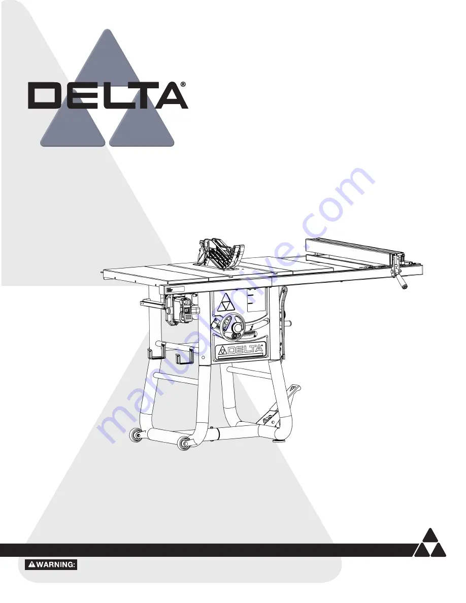
10-inch Contractor Table Saw 

www.DeltaMachinery.com 

Instruction Manual 

To reduce risk of serious injury, thoroughly read and comply with all warnings and instructions in this manual and on product. 

KEEP THIS MANUAL NEAR YOUR SAW FOR EASY REFERENCE AND TO INSTRUCT OTHERS. 

36-725 T2

Содержание 36-725 T2

Страница 1: ...Machinery com Instruction Manual To reduce risk of serious injury thoroughly read and comply with all warnings and instructions in this manual and on product KEEP THIS MANUAL NEAR YOUR SAW FOR EASY REFERENCE AND TO INSTRUCT OTHERS 36 725 T2 ...

Страница 2: ...TER GAUGE 30 USING BLADE GUARD ASSEMBLY 30 CHECKING FENCE ALIGNMENT 30 TRANSPORTING THE SAW 30 OPERATION 31 AVOID KICKBACK 31 STARTING AND STOPPING THE SAW 31 OVERLOAD PROTECTION 32 MAKING CUTS 32 RIP CUTS 33 BEVEL RIPPING 33 CROSSCUTTING 34 BEVEL CROSSCUTTING 35 MITER CUTS 35 COMPOUND MITER CUTS 35 LARGE PANEL CUTS 35 NON THROUGH CUTS 36 MAKING NON THROUGH CUTS 36 CUTTING AIDS AND ACCESSORIES 37 ...

Страница 3: ...stable Feet Fixed Wheels Hand Wheel Handle Tubular Stand Power Switch Saw Body F21 F22 F23 F17 F18 F19 F20 F21 F22 F23 Extension Wing Miter Gauge Blade Anti Kickback Pawls Riving Knife Rear Fence Rails Dust Chute F1 F2 F3 F4 F5 F6 F7 F8 F1 F2 F3 F4 Blade Guard Throat Plate Rail Spreader Bar Rip Fence Fence Guides Front Fence Rails Rip Fence Handle Lock Knobs ...

Страница 4: ...ct others If tool is loaned to someone also loan them these instructions If you have any questions or concerns relative to the use of your tool or the contents of this manual stop using the tool and contact Delta Power Equipment Corporation Customer Care at 1 800 223 7278 Some of the following symbols may be used in connection with this product Please study them and learn their meaning Proper inte...

Страница 5: ...turning the power tool on A wrench or a key left attached to a rotating part of the power tool may result in personal injury e Do not overreach Keep proper footing and balance at all times This enables better control of the power tool in unexpected situations f Dress properly Do not wear loose clothing or jewelery Keep your hair clothing and gloves away from moving parts Loose clothes jewelery or ...

Страница 6: ...ations and specific potential hazards will greatly minimize the possibility of accidents and injury Make sure all users are familiar with its warnings and instructions before using saw SEE POWER CONNECTION SECTION OF THIS MANUAL for instructions and warnings regarding power cords and connections TERMINOLOGY The following terms will be used throughout the manual and you should become familiar with ...

Страница 7: ...nto the saw blade c Never use the mitre gauge to feed the workpiece when ripping and do not use the rip fence as a length stop when cross cutting with the miter gauge Guiding the workpiece with the rip fence and the miter gauge at the same time increases the likelihood of saw blade binding and kickback d When ripping always apply the workpiece feeding force between the fence and the saw blade Use ...

Страница 8: ...utting a workpiece that is twisted knotted warped or does not have a straight edge to guide it with a mitre gauge or along the fence A warped knotted or twisted workpiece is unstable and causes misalignment of the kerf with the saw blade binding and kickback j Never cut more than one workpiece stacked vertically or horizontally The saw blade could pick up one or more pieces and cause kickback k Wh...

Страница 9: ...CKS Kickbacks can cause serious injury A kickback occurs when a part of the workpiece binds between the saw blade and the rip fence or other fixed object and rises from the table and is thrown toward the operator Kickbacks can be minimized by attention to the following conditions HOW TO REDUCE THE RISK OF KICKBACKS AND PROTECT YOURSELF FROM POSSIBLE INJURY Be certain that the rip fence is parallel...

Страница 10: ...e ELECTRICAL CONNECTION POLARIZED PLUGS EXTENSION CORDS KEEP the extension cord clear of the work area Position the cord so that it will not get caught on lumber tools or other obstructions while you are working with a power tool Failure to do so can result in serious personal injury Check extension cords before each use If damaged replace immediately NEVER use tool with a damaged cord since touch...

Страница 11: ...rton and packing materials until you have carefully inspected the contents assembled the machine and are satisfied that it operates correctly Compare package contents to Package Contents list and Hardware Package list prior to assembly to make sure all items are present Carefully inspect parts to make sure no damage occurred during shipping If any parts are missing damaged or pre assembled DO NOT ...

Страница 12: ...Feet 2 Fixed Wheels 2 Hand Wheel Handle 2 Rip Fence Handle 10 inch Blade Pre Installed Rail Spreader Bar Rear Fence Rails 2 Front Fence Rails 2 Fence Guides 2 PACKAGE CONTENTS UNPACKING PC1 PC1 PC2 PC2 PC3 PC3 PC17 PC17 PC4 PC4 PC5 PC5 PC6 PC6 PC7 PC7 PC8 PC8 PC9 PC9 PC10 PC10 PC11 PC11 PC12 PC12 PC13 PC13 PC14 PC14 PC16 PC16 PC18 PC18 PC19 PC19 PC20 PC20 PC15 PC15 ...

Страница 13: ... Hex Screw 12 Hardware Bag E M5 x 6mm Phillips Head Screw 1 Wire Clip 1 1 4 20 x 1 2 inch Button Head Hex Screw w Split Lock Washer 5 1 4 20 x 1 2 inch Hex Screw w Split Lock Washer 2 Hardware Bag F Rail Alignment Gauge 1 3 16 inch T Handle Allen Wrench 1 6mm Allen Wrench 1 3 16 inch Two Way Allen Wrench L Shape 1 HP20 HP16 HP17 HP8 HP18 HP19 HP21 HP22 HP23 HP6 HP15 HP9 HP10 HP7 HP7 HP13 HP1 HP2 H...

Страница 14: ...h 4 M6 x 72mm Carriage Bolts HP4 and 4 M6 Nylock Nuts HP5 and tighten See Figure 2 TOOLS REQUIRED FOR ASSEMBLY NOT INCLUDED Flat Head Screwdriver Phillips Head Screwdriver 8mm Wrench 10mm Wrench 12mm Open Ended Wrench 13mm Wrench Figure 1 9 16 inch Wrench 5 32 inch Allen Wrench Framing Carpenter s Square Combination Square Straight Edge Figure 2 Figure 3 Figure 4 FIXED WHEELS AND STATIONARY FEET H...

Страница 15: ...1 and 2 M5 Nylock Nuts HP10 in the two holes where the Rail Sections meet see Figure 6 3 Use supplied Rail Alignment Gauge HP20 to ensure the Rails are the proper distance from the top of the Table See Figure 7 4 Attach the Rear Fence Rails PC18 to the Table with 4 5 16 18 x 7 8 Hex Screw with Split Lock Washers HP7 Use the slot in the supplied Gauge to ensure the Rail is the proper distance from ...

Страница 16: ...18 x 1 1 8 inch Flat Countersunk Hex Screw HP15 and 5 16 18 Hex Flange Nuts HP13 4 for each wing See Figure 11 Be sure to confirm the Front and Rear Rails are level with the Extension Wings by using the Rail Alignment Gauge HP20 See Figure 5 9 3 Repeat this process on Front and Rear Rails for both Extension Wings 4 Attach the Spreader Bar PC17 to the outboard end of the Front and Rear Rails using ...

Страница 17: ... the left half Front Rail PC19 NOTE Leave these screws loose until the control box screws are started 3 Align the two holes in the Switch Box Bracket with the holes underneath the Front Rail PC19 see Figure 14 located on the left side of the saw Secure the Power Control Box to the Front Rail PC19 using 2 1 4 20 x 1 2 inch Hex Screw with Split Lock Washers HP19 Use a ruler to check that both Left a...

Страница 18: ... of the Saw as seen in Figure 18 The Rip Fence Handle is packaged individually and labeled accordingly please install as follows 1 Screw the Labeled Handle PC15 to the Rip Fence with the supplied Hex Wrench See in Figure 18 IMPORTANT Before raising Blade you MUST release Bevel Lock and tilt Blade 45 and remove styrofoam block under Motor Housing See Figure 19 PC14 PC14 PC15 INSTALLING THE HANDLES ...

Страница 19: ...ling Riving Knife Anti Kickback Pawls and Blade Guard Blade MUST be at 90 setting and raised to the maximum height See the RAISING AND LOWERING THE BLADE page 26 Figure 20 Figure 21 BLADE AND RIVING KNIFE A A A A A A A A ASSEMBLY PC8 PC8 To install Throat Plate PC8 lower Blade below Tabletop then carefully feed the Throat Plate PC8 slotted end first starting at the rear and moving to the front kee...

Страница 20: ...ade Guard Assembly and Anti Kickback Pawls and raise Riving Knife then reinstall the Anti Kickback Pawls and the Blade Guard Assembly NOTE Also reference Figure 40 page 28 To remove the blade guard assembly 1 Lift the Blade Guard Assembly Lock Lever D to the unlocked position 2 Rotate the Guard back and slide the Pin B from the Riving Knife Slot Figure 23 NOTE Check the Blade Guard for clearances ...

Страница 21: ...so On Board Storage for spare Saw Blades sold separately The Push Stick Spare Blade Blade should be stored protected to avoid injury Blade Wrench Anti Kickback Pawls and Blade Guard Storage areas are located on the Right Side of the Machine see Figure 25 On board storage for the Miter Gauge and Fence are located on the left side of the machine as seen in Figure 24 Figure 24 Figure 25 PC4 PC4 PC5 P...

Страница 22: ...andwheel counter clockwise and tilt the Blade to the 0 position until the Stop is reached 3 Using a Combination Square C check the angle of the Blade Face to the Table as shown in Figure 27 Confirm the blade is at 90 to the table 4 If the Blade is not perpendicular to the Table turn Hand wheel to slightly tilt the Blade away from the Stop Position then adjust the 90 Stop by adjusting the Set Screw...

Страница 23: ...lel alignment use the two set screws B see Figure 28 Clockwise adjust riving knife to the right Counter clockwise adjust riving knife to the left If needed use the set screws to align the riving knife with blade face and the square 6 Fully tighten the two hex head cap screws 7 Replace throat plate blade guard and anti kickback assemblies before use If any dragging or binding of the workpiece is en...

Страница 24: ...miter gauge bar NOTE The set screws should extend just beyond the side of the bar ADJUSTING THE MITER GAUGE SCALE 1 Use the supplied 3 16 inch two way Allen wrench to loosen the three Phillip screws located in the back of the miter gauge see in Figure 31 A 2 Loosen the knob see in Figure 31 B 3 Adjust the detent plate so that the indicator measures the correct angle see in Figure 31 C 4 Once lined...

Страница 25: ...but a little less If the fence is further out of parallel turn the set screw in the opposite direction 1 Move fence over the cast iron table and secure to the guide tube by lowering the fence clamping lever 2 Use a square to check that the fence face is perpendicular to the table 3 If the fence face is not perpendicular to the table release the clamping lever and slightly adjust one of the slotted...

Страница 26: ... the lock knob B counterclockwise and turn the hand wheel clockwise A pointer on the front of the saw indicates the angle of tilt in 1 2 degree increments 2 To lock the saw blade at your desired angle tighten the lock knob by rotating it clockwise ONLY a small amount of force is required to lock the blade raising mechanism securely Any added force merely puts unnecessary strain on the locking devi...

Страница 27: ...gure 39 SELECTING AND STORING SAW BLADES Riving knives MUST be matched to saw blade dimensions in order to function effectively The saw blade furnished with your new saw is a 10 inch 254mm combination blade used for cross cutting across the grain and ripping with the grain through the workpiece The arbor hole of the blade is 5 8 inch 16mm diameter This blade will produce a good quality cut for mos...

Страница 28: ... through cuts when the blade does not penetrate the top of the workpiece the riving knife should be in the lowered position and anti kickback pawls and guard removed TO RAISE OR LOWER THE RIVING KNIFE 1 Remove the throat plate and raise blade to the full height above the table 2 Locate the locking cam lever near the base of the riving knife A 3 Rotate the cam lever by turning clockwise to unlock a...

Страница 29: ...CUT Figure 44 Figure 45 CHECKING BLADE PARALLELISM TO MITER GAUGE GROOVE HEEL See Figures 44 45 Blade A MUST be parallel to miter gauge groove so that wood does not bind resulting in kickback Failure to do so could result in serious personal injury To reduce risk of injury from kickback align miter gauge groove to blade A following any blade adjustments DO NOT loosen any screws for this adjustment...

Страница 30: ...ur rip fence place the fence adjacent to miter slot and lock the fence in place If the fence is not aligned to the miter slot from the front to the back see instructions for aligning rip fence on page 25 of this manual If you are not able to successfully align the rip fence replace the rip fence or call DELTA Customer Service at 1 800 223 7278 NOTE Make sure the saw is OFF and the blade lowered be...

Страница 31: ...tion Is the blade set at the proper height If ripping is the rip fence parallel to the blade and securely locked in position If crosscutting is the miter gauge knob tight If making through cuts with a standard blade are the blade guard riving knife and anti kickback pawls properly attached and properly functioning with both guards contacting the table surface Is there proper clearance and support ...

Страница 32: ...than the speed of this tool To avoid kickback make sure one side of the workpiece is securely against the rip fence during any rip cut and hold the workpiece firmly against the miter gauge during any miter cut DO NOT attempt compound miter cuts with blade beveled and miter fence angled until you are thoroughly familiar with the basic cuts and understand how to avoid kickback Avoid bevel rip cuts w...

Страница 33: ...n 8 Stand alongside the workpiece on the same side of the blade as the fence 9 Hold the workpiece flat on the table and against the fence A The workpiece MUST have a straight edge against the fence and MUST NOT be warped twisted or bowed See proper hand position in Figure 50 10 Let blade build up to full speed before moving workpiece into the blade 11 Both hands can be used while starting the cut ...

Страница 34: ...orkpiece on the same side of the blade as the miter gauge 7 Hands MUST remain at least 6 inches from blade throughout entire cut If workpiece is too small to KEEP hands at least 6 inches away from the blade select a larger workpiece or attach an auxiliary face to the miter gauge and attach workpiece to auxiliary face For instructions about making auxiliary faces see Cutting Aids section on page 37...

Страница 35: ...es less than 45 may force the blade guard assembly into the saw blade causing damage to the blade guard assembly and personal injury Before starting the motor test the operation by feeding the workpiece into the blade guard assembly If the blade guard assembly contacts the blade place the workpiece under the blade guard assembly but not touching the blade before starting the motor Certain workpiec...

Страница 36: ...back pawls 6 Place riving knife in lowered position See RIVING KNIFE POSITION section on page 28 7 Set blade to correct depth for workpiece 8 Depending on shape and size of wood use either rip fence or miter gauge 9 Plug saw into power source and turn saw on 10 Let blade build up to full speed before moving workpiece into blade 11 ALWAYS use push blocks push sticks and or featherboards when making...

Страница 37: ...ed for special cuts such as ripping material that is thin enough to slide under the rip fence provided with your saw or when a taller rip fence is necessary to complete your cut To add an auxiliary wood facing to one or both sides of the rip fence select a piece of wood with smooth surfaces Attach the wood to the rip fence with two clamps See Figure 56 For most work 3 4 inch 19mm or 1 inch 25mm st...

Страница 38: ...u can angle the hole to provide a more comfortable grip on the handle 3 Glue a piece of rough or soft material such as sandpaper or rubber to the bottom of the block to grip the workpiece old mouse pads work well See Figure 59 Figure 59 FLIP DOWN FENCE Use the flip down fence when cutting thin stock that might normally slide underneath the regular rip fence or in which the blade guard would normal...

Страница 39: ...op rotating before removing stock 6 Reset rip fence and cut spaced rips into workpiece to allow approximately 1 4 inch fingers and 1 8 inch spaces between fingers To avoid binding between the workpiece and the blade make sure a horizontal feather board presses ONLY on the uncut portion of the workpiece in front of the blade Dimensions for making a typical featherboard are shown in Figure 60 Make y...

Страница 40: ...AYS position the cut off gauge in front of the saw blade Figure 62 JIGS Jigs may be created with a variety of special set ups to control particular workpiece shapes for particular cuts Guidance on how to make specialized jigs can be found in woodworking and carpentry websites and publications DO NOT attempt to create or use a jig unless you are thoroughly familiar with table saw safety DO NOT use ...

Страница 41: ...area free of dust and debris buildup Blow out area regularly with compressed air NOTE If the riving knife clamp can t move freely have the saw serviced by authorized DELTA service center personnel WORM GEARS KEEP the worm gears free of dust and debris buildup Blow out area regularly with compressed air Use a lithium based multipurpose grease as needed on these gears CLEAN SAWDUST BUILDUP OUT OF SA...

Страница 42: ...sing the supplied 3 16 inch Two Way Allen Wrench L Shape HP23 See Figure 64 2 Rotate the dust port downward and clear any sawdust or woodchips that may be inside the dust chute See Figure 65 3 When finished rotate the dust port back to its original position and secure the hex screw back in place MAINTENANCE ...

Страница 43: ...na com How do I get Warranty work done on my product Keep a copy of your receipt to present to our Service Center if any issues arise with your machine A complete line of accessories is available from your DELTA Supplier DELTA Factory Service Centers and DELTA Authorized Service Centers Please visit our Web Site www DeltaMachinery com for an online catalog or for the name or your nearest supplier ...

Страница 44: ...ted warranty is Company s sole warranty and sets forth the customer s exclusive remedy with respect to defective products all other warranties express or implied whether of merchantability fitness for purpose or otherwise are expressly disclaimed by Company except as expressly stated in this warranty statement Some states do not allow the exclusion or limitation of incidental or consequential dama...

Страница 45: ...2651 New Cut Road Spartanburg SC 29303 800 223 7278 www DeltaMachinery com Copyright 2022 Delta Power Equipment Corporation DPEC005496 Rev 22 02 11 2022 ...

Отзывы: